Formation grinding wheel, grinding bed and grinding formation arc edge ceramic tiles

A grinding wheel and arc edge technology, which is applied to grinding machines, machine tools suitable for grinding the edge of workpieces, abrasives, etc., can solve the problems of complex process, high cost, and low efficiency, and achieve high efficiency, low cost, and simple structure.

Inactive Publication Date: 2014-12-03
TIANJIN BEILITAI CERAMIC
10 Cites 0 Cited by

AI-Extracted Technical Summary

Problems solved by technology

[0003] In view of the defects in the above-mentioned prior art, the shaped grinding wheel of th...

Method used

For making profiled grinding wheel 10 when in use, more durable, reduce the temperature when profiled grinding wheel 10 grinds, in one embodiment of the present invention, concave arc angle 40,50 and disk surface 20,30 A plurality of parallel water injection grooves 42, 52 are provided at the included angle. In order to improve, when the forming grinding wheel 10 is running at high speed, the cooling...

Abstract

The invention provides a formation grinding wheel and relates to the technical field of ceramic tile mechanical treatment. The formation grinding wheel is applied in the polishing process of arc edge tiles of small size interior wall tiles. According to the invention, an angle or two angles formed by the grinding wheel surface of a formation grinding wheel and a disk surface on one side or disk surfaces on the two sides is/are an inward concave arc-shaped angle or inward concave arc-shaped angles; an inward concave arc-shaped formation blade or inward concave arc-shaped formation blades is/are formed on one side edge or two side edges of the grinding wheel surface, so that the problems of complex operation, low efficiency and high cost in arc edge processing and formation of the conventional ceramic tiles are solved; therefore, the formation grinding wheel provided by the invention is simple in structure and convenient and quick in ceramic tile polishing and can improve efficiency and reduce processing cost.

Application Domain

Edge grinding machinesCovering/linings +1

Technology Topic

Shape formationCeramic tiles +6

Image

  • Formation grinding wheel, grinding bed and grinding formation arc edge ceramic tiles
  • Formation grinding wheel, grinding bed and grinding formation arc edge ceramic tiles
  • Formation grinding wheel, grinding bed and grinding formation arc edge ceramic tiles

Examples

  • Experimental program(1)

Example Embodiment

[0021] Below will combine accompanying drawing of the present invention Figure 1~5 , clearly and completely describe the technical solution of the present invention, obviously, the described embodiments are only some embodiments of the present invention, not all the embodiments. Based on the embodiments of the present invention, all other embodiments obtained by persons of ordinary skill in the art without creative efforts fall within the protection scope of the present invention.
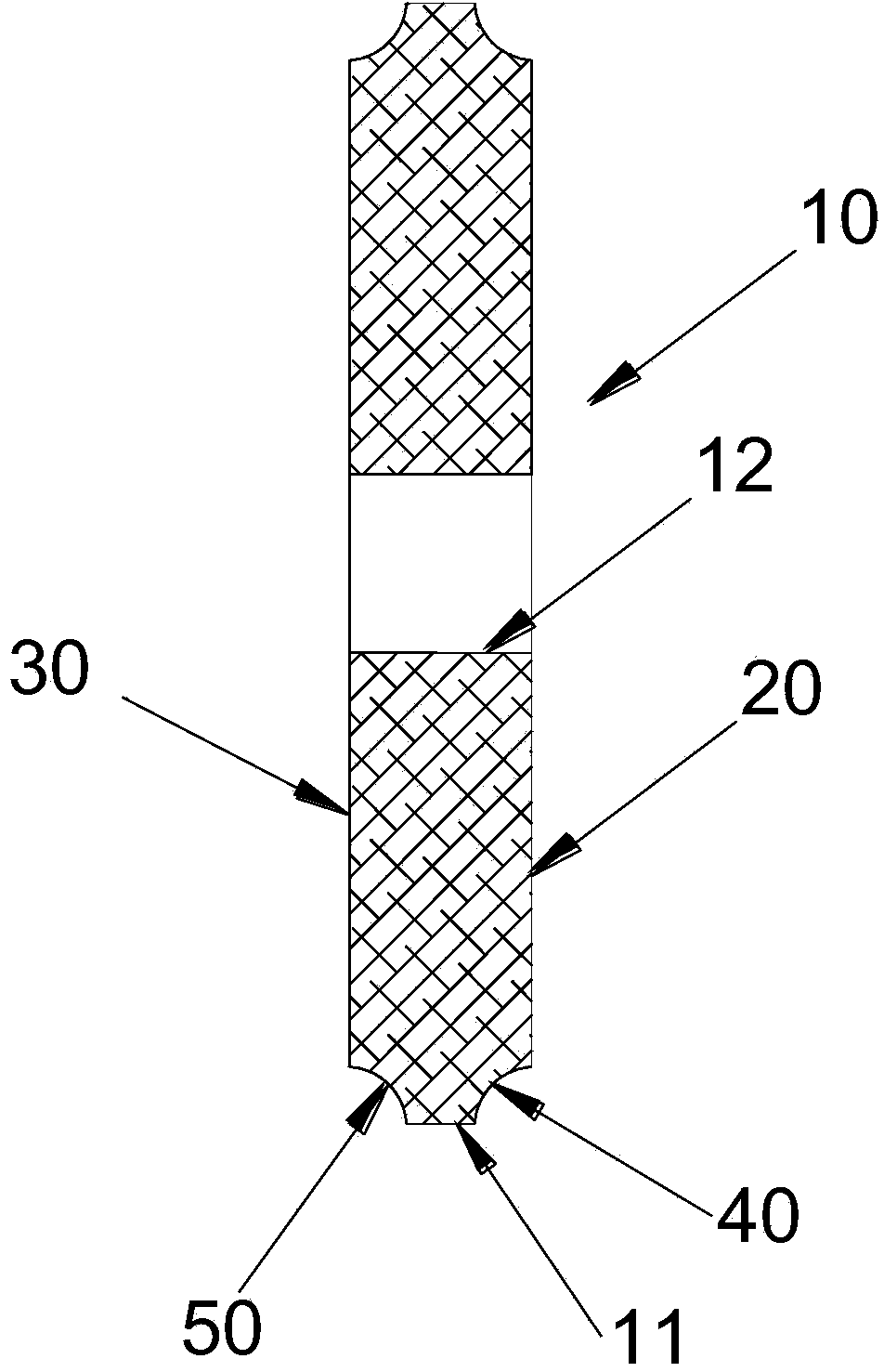
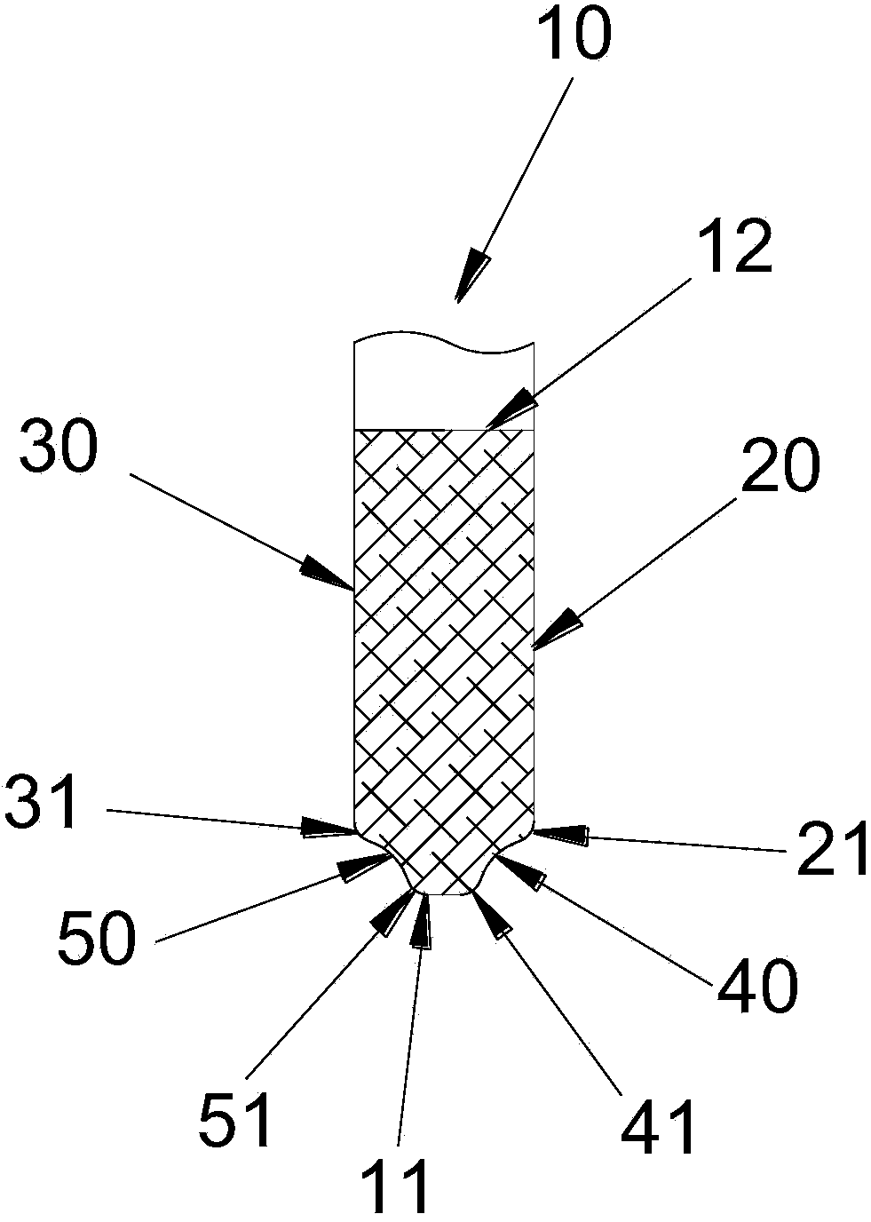
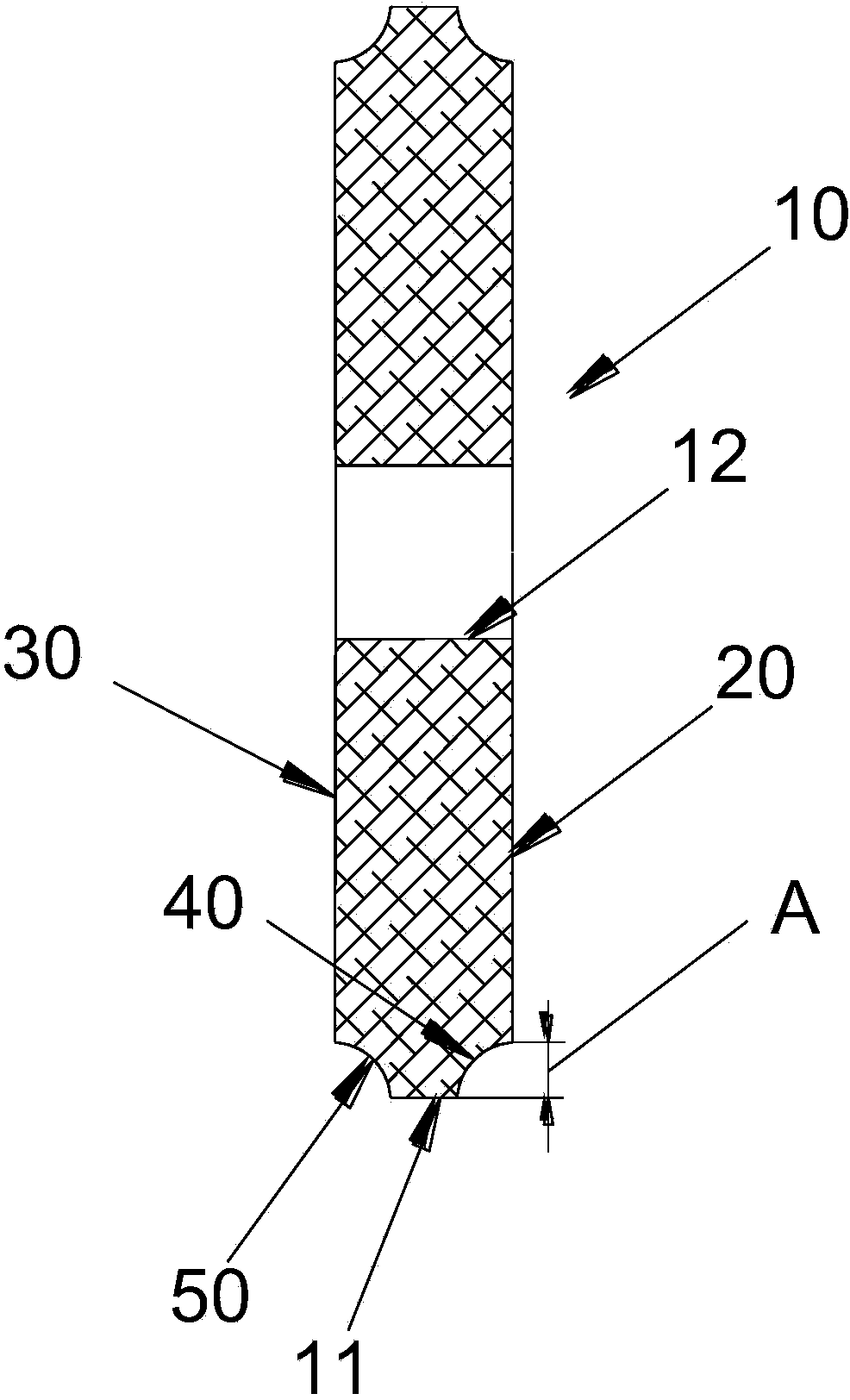
[0022] like figure 1 As shown, in one embodiment of the present invention, profile grinding wheel 10 is made of diamond or alloy steel. The outer diameter of forming grinding wheel 10, and the diameter of grinding wheel surface 11 are The diameter of the inner support shaft hole 12 is preferably 60 mm. The shape of the included angle between the grinding wheel surface 11 and the two side disk surfaces 20, 30 is made into concave arc angles 40, 50, and the concave arc angle forming edge is formed on the grinding wheel surface 11 side or both sides edges. In order to improve the durability of the profiled grinding wheel 10, the included angles 41, 51 between the concave arc angles 40, 50 and the grinding wheel surface 11 are impact-resistant arc angles, and the impact-resistant arc angles are 30° or 60°. The included angles 21 and 31 between the concave arc angle 40 (or 50 ) and the disk surface 20 (or 30 ) are anti-shock arc angles, and the anti-shock arc angles are 30° or 60°. ,like image 3 As shown, in one embodiment of the present invention, the distance "A" projected from the concave arc angles 40 and 50 in the direction of the disc surfaces 20 and 30 is 6.8-9.5 mm.
[0023] In order to make the profiled grinding wheel 10 more durable during use and reduce the temperature of the profiled grinding wheel 10 during grinding, in one embodiment of the present invention, the angles between the concave arc angles 40, 50 and the disk surfaces 20, 30 Set up a plurality of parallel water injection grooves 42,52. In order to improve, when the forming grinding wheel 10 is running at high speed, the cooling water flows downward in multiple parallel water injection grooves 42, 52. Fill the gutter for the dovetail shape. In this way, it can avoid the water in the water injection tank being thrown out of the tank due to the action of centrifugal force during the rotation process, so that more water can be stored, so that more cooling water flows into the cutting and grinding parts to cool them down better.
[0024] In order to facilitate the dynamic balance adjustment of the shaped grinding wheel 10 , in one embodiment of the present invention, a plurality of concentrically arranged balance weight groove rails are provided on one or both disk surfaces 20 , 30 of the shaped grinding wheel 10 . When dynamic balance adjustment is required, the counterweight can be installed in the balance counterweight groove.
[0025] Thereby, the forming grinding wheel 10 of the present invention can be directly installed on a grinding machine during use, and can simultaneously perform circular arc forming on the inner legs of two ceramic tiles arranged in parallel.
[0026] like Figure 5 As shown, an embodiment of the present invention also provides a grinding machine, including a profiled grinding wheel 10 installed in the middle of the grinding machine, a steel plate 60 , straight-edged ceramic tiles 70 , and a conveyor belt 80 . The shaped grinding wheel 10 is the above-mentioned shaped grinding wheel 10, which is installed on the grinding and cutting equipment in the middle of the grinding machine. The size of the steel plate should be corresponding to the size of the conveyor belt 80, and the straight edge ceramic tile 70 is placed on the conveyor belt, and the placement direction should make the straight edge line of the straight edge ceramic tile 70 parallel to the cutting surface.
[0027] like Figure 5 As shown, the straight-edge ceramic tile 70 placed on the conveyor belt is driven by the conveyor belt 80 into the cutting surface of the cutting equipment, and the forming grinding wheel 10 set in the grinding and cutting equipment runs quickly, grinding the arc along the edge of the straight-edge ceramic tile 70 , as the ceramic tile moves forward, its arc edge is ground and cut into shape, so that the shape of the grinding place of the shaped grinding wheel 10 is the same as the arc edge of the arc edge brick.
[0028] An embodiment of the present invention also provides an arc-edge ceramic tile, which is an arc-edge ceramic tile formed by grinding the forming grinding wheel in any one of the embodiments, and the arc-shaped edge of the arc-edge ceramic tile is in line with the shape The concave arc-shaped edges of the grinding wheel 10 are consistent.
[0029] The above is only a specific embodiment of the present invention, but the scope of protection of the present invention is not limited thereto. Anyone skilled in the art can easily think of changes or substitutions within the technical scope disclosed in the present invention. Should be covered within the protection scope of the present invention. Therefore, the protection scope of the present invention should be based on the protection scope of the claims.

PUM

PropertyMeasurementUnit
Diameter250.0mm

Description & Claims & Application Information

We can also present the details of the Description, Claims and Application information to help users get a comprehensive understanding of the technical details of the patent, such as background art, summary of invention, brief description of drawings, description of embodiments, and other original content. On the other hand, users can also determine the specific scope of protection of the technology through the list of claims; as well as understand the changes in the life cycle of the technology with the presentation of the patent timeline. Login to view more.

Similar technology patents

Photoelectric sensor for position of sun

InactiveCN101650173AEffective tracking range expandedSimple structure
Owner:WUHAN UNIV OF TECH

Magnetic cooling apparatus and control method thereof

ActiveUS20130180263A1simple structure
Owner:SAMSUNG ELECTRONICS CO LTD

Dual-Drivetrain of Power-Assist Vehicle

InactiveUS20100181130A1enhance uphill momentumsimple structure
Owner:CHOU WEN CHENG

Classification and recommendation of technical efficacy words

Why Eureka
Try Eureka