
plastic cutting machine

A technology of plastic hot cutting machine and roller shaft, which is applied in metal processing and other directions, can solve the problems of plastic particles being susceptible to moisture, waste of energy, and increase of enterprise costs, so as to solve the problem of water pollution, avoid the waste of funds, and solve the problem of funds.

Inactive Publication Date: 2017-04-05
卢寿同
View PDF7 Cites 2 Cited by
  • Summary
  • Abstract
  • Description
  • Claims
  • Application Information

AI Technical Summary

Problems solved by technology

The disadvantages are: 1. Due to the direct contact with water during the cooling process, the plastic particles are very easy to be affected by moisture, especially in summer, the air humidity is high, and it can only be stored for more than ten days at most, and bubbles will occur inside the particles, resulting in the plastic particles not being used normally. , had to be reprocessed as raw material
waste energy, increase cost
2. During the water cooling process, the liquid plastic is in direct contact with water, causing serious water pollution, failing to meet environmental protection requirements, and the cooling water cannot continue to be used
3. The particles come out into uneven and irregular cylindrical particles
At present, there are also large-scale equipment on the market, but the price ranges from more than 100,000 yuan to hundreds of thousands of yuan. The purchase of large-scale equipment will inevitably increase the cost of the enterprise.
At the same time, the original old equipment can only be eliminated, resulting in a waste of resources and funds

Method used


Image

  • plastic cutting machine
  • plastic cutting machine
  • plastic cutting machine

Examples


Embodiment Construction

[0012] The present invention will be described in further detail below in conjunction with the accompanying drawings: the present embodiment is implemented on the premise of the technical solution of the present invention, and detailed implementation is provided, but the protection scope of the present invention is not limited to the following embodiments.

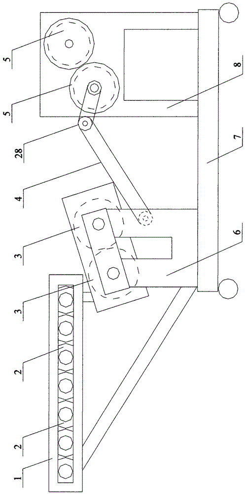
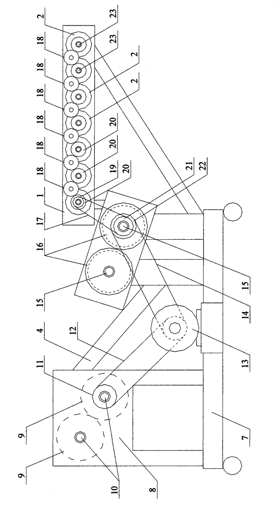
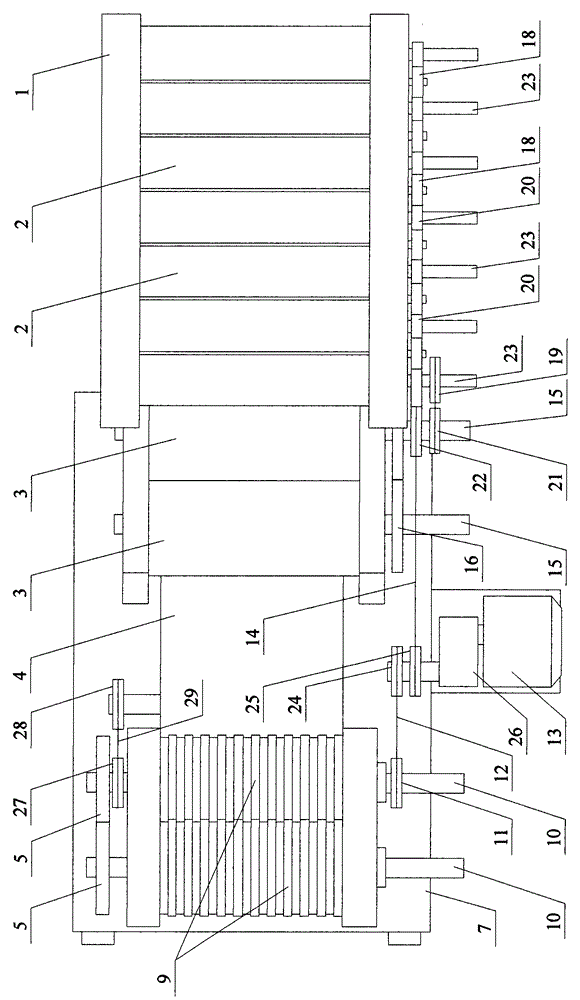
[0013] Such as Figure 1 ~ Figure 3 As shown, a plastic hot cutting machine involved in this embodiment includes: a roller frame 1, a hollow codirectional water-cooled chrome-plated shaft roller 2, two chrome-plated large pair of roller rollers 3, a rubber conveyor belt 4, two Roller cutter gear 5, first support 6, base 7, second support 8, cooling roller cutter 9, cooling inlet and outlet water pipe 10 of roller cutter, first sprocket wheel 11, first chain 12, motor 13, second Chain 14, roller inlet and outlet water pipe 15, two roller gears 16, transmission belt 17, transmission gear 18, first pulley 19, shaft roller gea...


PUM


Abstract

The invention provides a plastic hot cutting machine, and belongs to the technical field of plastic machining equipment. One end of a hollow same-direction water cooling chrome-plated shaft roller is connected with a shaft roller water input and output pipe, two chrome-plated large-paired-roller shaft roller cylinders are of a hollow structure, a roller cylinder water input and output pipe is connected to each chrome-plated large-paired-roller shaft roller cylinder, cooling paired-roller knives are of a hollow structure, a cooling paired-roller knife water input and output pipe is connected to each cooling paired-roller knife, one pair of cooling paired-roller knives is made of chrome-12 steel pipes with the diameter of 10 cm, and isometric concave and convex grooves are formed in the outer faces of the cooling paired-roller knives. According to the machine, the technical problem that plastic particles are easily affected with damp in the rainy season and cannot be normally used is solved, the problem that plastic is in direct contact with water, and water pollution is caused is solved, original mechanical devices are fully utilized, a large amount of fund waste is avoided, resources are saved, and the fund problem is solved. Meanwhile, products are regular small-cuboid particles, and multiple kinds of plastics exist and are suitable for the plastic hot cutting machine.

Description

technical field [0001] The invention relates to a plastic hot cutting machine, which belongs to the technical field of hot cutting machines. Background technique [0002] In the prior art: the melted plastic raw material extrudes liquid 200°C thermal plastic filaments from the outlet hole and is directly cooled by a flowing cold water tank to become solid 30°C-50°C plastic filaments. The disadvantages are: 1. Due to the direct contact with water during the cooling process, the plastic particles are very easy to be affected by moisture, especially in summer, the air humidity is high, and it can only be stored for more than ten days at most, and bubbles will occur inside the particles, resulting in the plastic particles not being used normally. , had to be reprocessed as raw materials. Waste of energy and increase costs. 2. During the water cooling process, the liquid plastic is in direct contact with water, causing serious water pollution, failing to meet environmental prot...

Claims


Application Information

Patent Timeline
Patent Type & Authority Patents(China)
IPC IPC(8): B29B9/06B29C47/34B29C47/88B29C43/24B29C43/52B26D1/12B26D7/08B29C48/355
CPCB29C48/914
Inventor 卢寿同
Owner 卢寿同
Learn More