
Pumping conveying vehicle

A technology for transporting cars and vehicles, which is applied in the field of suction equipment, which can solve problems such as time-consuming and power-consuming, inflexible structure, time-consuming and labor-intensive problems, and achieve the effects of avoiding dust and noise pollution, superior performance and flexible operation

Active Publication Date: 2014-12-03
福建海山机械股份有限公司
View PDF5 Cites 13 Cited by
  • Summary
  • Abstract
  • Description
  • Claims
  • Application Information

AI Technical Summary

Problems solved by technology

[0003] Patent ZL201020170173 discloses an intelligent multifunctional combined sewage suction truck, which can realize the suction, transportation, and unloading of materials such as sewage, sludge, and gravel, but the following problems cannot be effectively solved: 1) due to the structure and performance of the vacuum unit Due to the limitation, the suction and excavation of compacted materials cannot be realized, and the related work needs to be done manually; 2) There is no auxiliary unloading device in the storage bin, and it can only be unloaded by forced discharge, which takes a lot of time and power, and for the solid materials adhered to the storage bin, it cannot be unloaded cleanly; 3) Although the suction arm can realize rotation and lifting actions, but the structure is not flexible, and manual operation of the suction hose is still required to achieve Precise positioning, time-consuming and labor-intensive
Other patents that have been disclosed so far are still focused on the field of traditional sewage suction trucks. The new equipment and technology that integrates excavation, suction, and transportation functions mentioned in this patent are not mentioned.

Method used


Image

  • Pumping conveying vehicle
  • Pumping conveying vehicle
  • Pumping conveying vehicle

Examples


Embodiment Construction

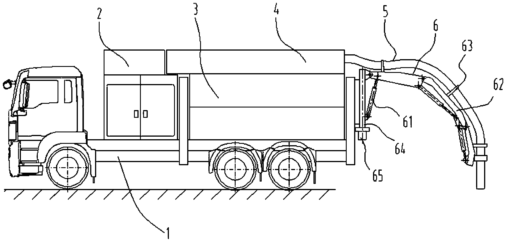
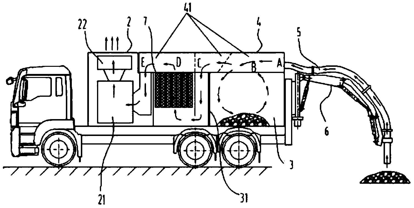
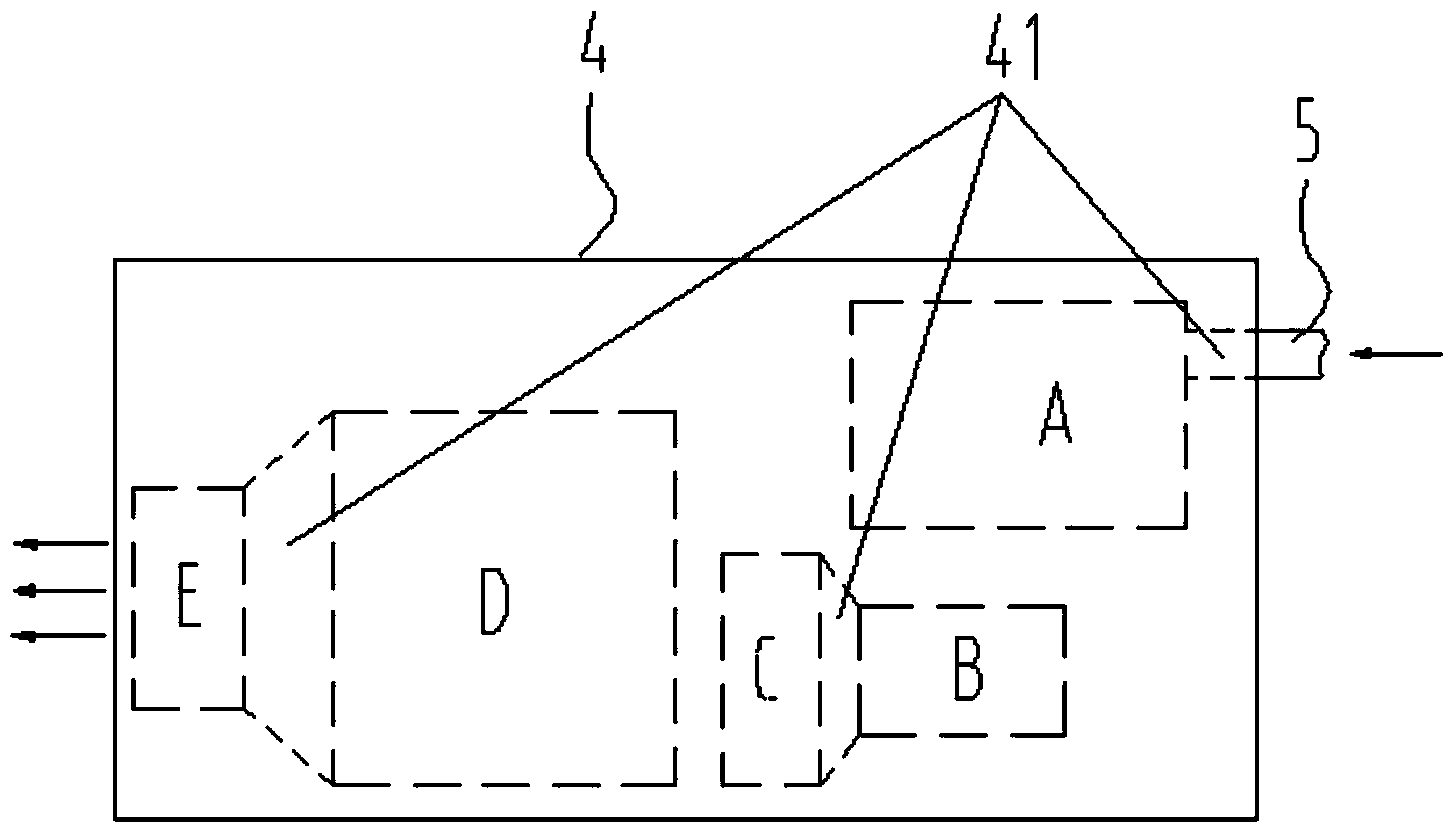
[0030] Such as figure 1 and figure 2 As shown, the present invention provides a suction vehicle, which is applied to the suction, transportation and unloading of materials. The suction vehicle includes a vacuum unit 2, a filter device 7, a storage bin 3, a suction Suction arm 6 and discharge device 8 (such as Figure 6 shown); the filter device 7 is respectively connected with the vacuum unit 2 and the storage bin 3; the top of the storage bin 3 is provided with an openable storage bin top cover 4, and the inside of the storage bin top cover There is a passage 41 for air flow transmission, which makes the filter device 7 communicate with the storage bin 3; the suction pipe 5 is attached to the suction arm 6, and is spatially positioned with the movement of the suction arm 6. One end of the pipe 5 is connected to the top cover 4 of the storage bin, and the other end is connected to the material to be sucked; the discharge device 8 is arranged on both sides or the bottom...


PUM


Abstract

The invention provides a pumping conveying vehicle. The pumping conveying vehicle comprises a vacuum unit, a filtering device, a material storing chamber, a pumping arm and an unloading device which are arranged on a vehicle chassis, wherein the filtering device is respectively communicated with the vacuum unit and the material storing chamber; a material storing chamber top cover which can be opened is designed at the top of the material storing chamber, a channel where air flow is transmitted is designed in the material storing chamber top cover, and the filtering device is communicated with the material storing chamber by the aid of the channel; a pumping tube is attached to the pumping arm, spatial orientation is performed with the movement of the pumping arm, the vacuum unit passes through the filtering device and the channel in the material storing chamber top cover, an inner cavity of the material storing chamber is pumped to form a semi-vacuum state, by means of pressure difference of the inner cavity of the material storing chamber and atmosphere, the pumping arm drives the pumping tube to move so that a material to be pumped is pumped into the material storing chamber, and during unloading, the unloading device turns over the material storing chamber so that the material is unloaded by the aid of gravity of the material.

Description

technical field [0001] The invention relates to a suction device, in particular to a special vehicle for excavating, suctioning, transporting and unloading soil, gravel, powder and other materials by means of suction. Background technique [0002] With the development and expansion of the city, there are more and more related municipal engineering construction and maintenance work, such as civil construction, water supply, power supply, gas supply and other municipal pipe network construction, as well as building protection and public facility maintenance. These tasks require very precise excavation work, because these work sites often have interlaced cables, pipelines, etc., and damage must be prevented; in addition, due to urban space constraints, many general-purpose excavation equipment cannot be driven into the construction site or for underground construction. However, the efficiency of traditional manual excavation is very low, and a large amount of soil or sand produ...

Claims


Application Information

Patent Timeline
Patent Type & Authority Applications(China)
IPC IPC(8): B60P3/00B65F3/00
Inventor 黄向阳闫炳雷
Owner 福建海山机械股份有限公司
Learn More