Gas distributor, gasifier and carbon-containing material gasification method

A technology of gas distributor and gasifier, which is applied in the field of gas distributor, gasifier and carbon-containing material gasification, can solve the problems of slow heat transfer, low gas velocity, material leakage and uneven flow of gasification agent, etc.

Active Publication Date: 2014-12-03
ENN SCI & TECH DEV
View PDF9 Cites 9 Cited by
  • Summary
  • Abstract
  • Description
  • Claims
  • Application Information

AI Technical Summary

Problems solved by technology

In the prior art, gas distributors used in gasification furnaces are usually porous plate distributors, which are divided into two types: flat plate distributors and conical distributors; among them, due to the presence of leaking material and gasification agent Problems such as uneven flow are rarely used in actual production; therefore, the commonly used perforated plate distributor is a conical distributor. The conical distributor includes a conical distribution plate, and several small holes are arranged on the conical distribution plate. The gasification agent enters the gasifier through each small hole to react with the granular coal to convert the granular coal into gas
[0004] For low-pressure coal gasification technology, due to the relatively low pressure in the gasifier, the gasification agent entering the furnace space above the conical distributor can flow at a relatively high gas velocity, so that the granular coal can be fully gasified However, for medium and high pressure coal gasification technology, due to the relatively high pressure in the gasifier, the gasification agent entering the furnace space through the small holes is severely compressed, resulting in the gasification of the gasification agent entering the furnace space The flow rate is low and the fluidity is poor, especially in the gasification process of coal with large particle size, it is easy to form a flow dead zone in the conical distributor; in addition, the pressure increases the gasification intensity of the gasifier , that is, the processing amount of granular coal increases. For the gasification reaction of granular coal and superheated steam, the heat required increases and the oxygen consumption increases. The speed is low, the fluidity is poor, and the heat transfer of granular coal and oxygen combustion is slow, which leads to local high temperature areas in the above-mentioned furnace space, which in turn leads to the occurrence of granular coal sintering or slagging in the above-mentioned furnace space.
[0005] To sum up, when the gasifier adopts the above-mentioned conical sparger for coal gasification, it is easy to form a flow dead zone in the gasifier, and phenomena such as sintering and slagging occur

Method used


Image

  • Gas distributor, gasifier and carbon-containing material gasification method
  • Gas distributor, gasifier and carbon-containing material gasification method
  • Gas distributor, gasifier and carbon-containing material gasification method

Examples


Embodiment 1

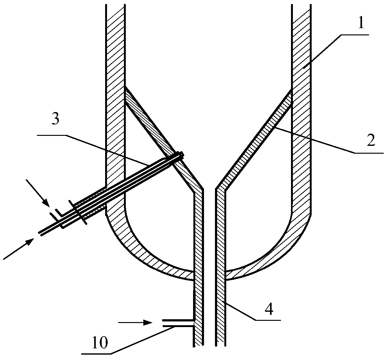
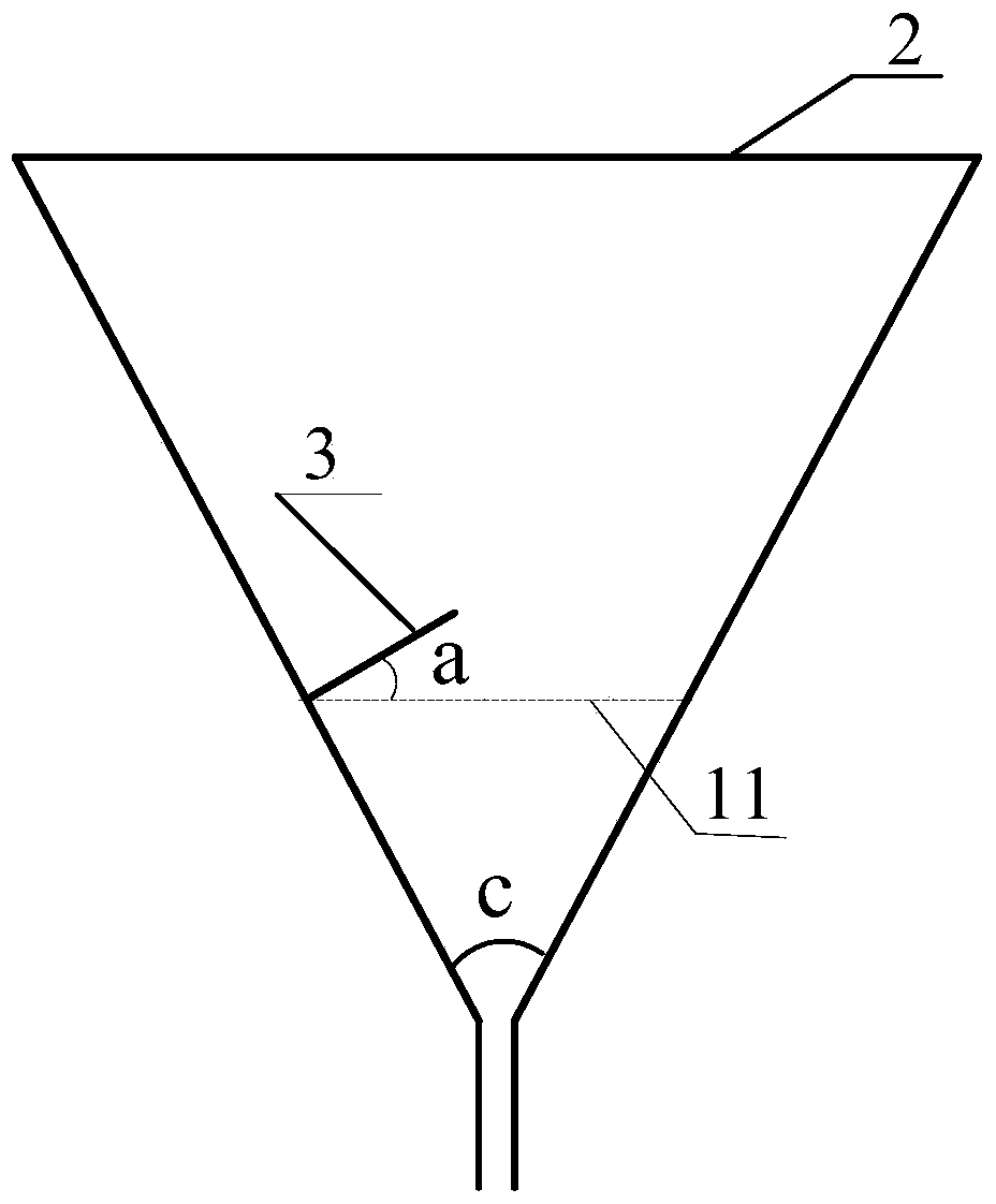
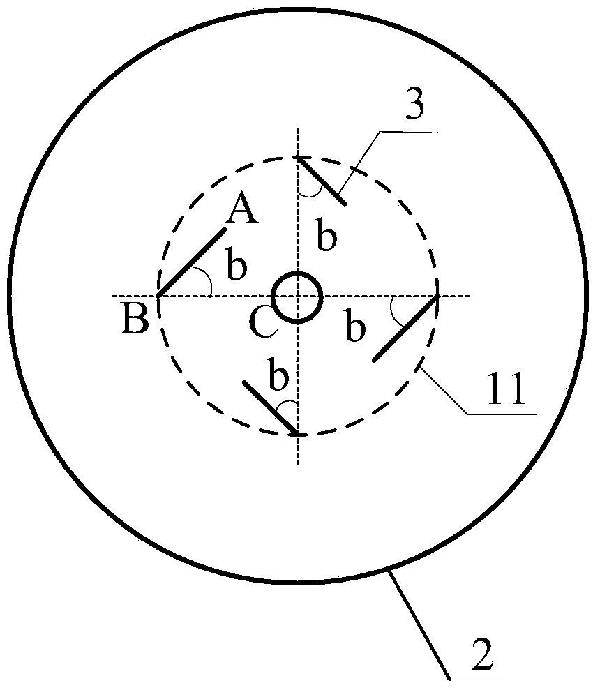
[0048] see figure 1 , figure 2 , image 3 and Figure 4, the embodiment of the present invention provides a gas distributor, including: a conical distribution plate 2 with a slag discharge port at the bottom, at least one nozzle 3 that runs through the conical distribution plate 2, and enters the cone through each nozzle 3 The gasification agent in the space surrounded by the shaped distribution plate 2 forms a vortex; wherein, each nozzle 3 includes: a central inner tube 8, at least one outer tube 7 sleeved on the central inner tube 8, a central inner tube 8 and An annular gap 9 is formed with at least one outer tube 7 .

[0049] When the above-mentioned gas distributor is used to gasify carbon-containing materials, the gasification agent enters the space surrounded by the conical distribution plate 2 through each nozzle 3 and forms a vortex, and the carbon-containing material enters the vortex formed by the gasification agent. , will flow with the gasification agent, an...

Embodiment 2

[0064] The embodiment of the present invention also provides a gasifier, including: a gasifier shell 1, a feed pipeline and a gas outlet pipeline respectively communicated with the gasifier shell 1, and the gasifier shell 1, Any gas distributor mentioned in the above technical solution. Specifically, please continue to figure 1 , the conical distribution plate 2 is installed through the gasifier shell 1, the slag discharge port of the conical distribution plate 2 is connected with the slagging pipe 4, and the slagging pipe 4 passes through the gasifier shell 1 downwards, and each nozzle The pipes 3 respectively pass through the preset holes on the gasifier shell 1 and the installation holes on the conical distribution plate 2 , and the gas outlets of each nozzle 3 protrude from the inner surface of the conical distribution plate 2 .

[0065] When the above-mentioned gasification furnace is used to gasify carbon-containing materials, the gasification agent enters the furnace s...

Embodiment 3

[0067] The embodiment of the present invention also provides a carbonaceous material gasification method, comprising:

[0068] 101. Pass the gasification agent into the furnace space above the conical distribution plate 2 in the gasification furnace through each nozzle 3, and the gasification agent entering the furnace space forms a vortex;

[0069] 102 Add carbonaceous materials into the gasification furnace from the feed pipeline, the carbonaceous materials flow with the vortex, and undergo gasification reaction with the gasification agent, the generated combustible gas is discharged out of the gasifier shell 1 through the gas outlet pipeline, and the generated Waste slag is discharged through the slag discharge port.

[0070]In more detail, when the carbonaceous material is gasified, the gasification agent enters the furnace space above the conical distribution plate 2 in the gasification furnace through each nozzle 3, and forms a vortex, and the carbonaceous material is di...


PUM

PropertyMeasurementUnit
diameteraaaaaaaaaa
porosityaaaaaaaaaa

Abstract

The invention discloses a gas distributor, a gasifier and a carbon-containing material gasification method, and relates to the technical field of carbon-containing material gasification. The gas distributor comprises a conical distribution plate in the bottom of which a slag discharge hole is formed and at least one spray pipe arranged on the conical distribution plate in a penetrating manner, wherein a gasifying agent entering the space encircled by the conical distribution plate through each spray pipe forms vortex; and each spray pipe includes a central inner pipe and at least one outer pipe sleeving the central inner pipe, wherein an annular space is formed between the central inner pipe and the at least one outer pipe. When the gas distributor is used for a carbon-containing material gasification technology, the phenomena of a flowing dead zone formed in the gasifier, sintering and slagging of carbon-containing materials and the like can be relieved.

Description

technical field [0001] The invention relates to the technical field of gasification of carbon-containing materials, in particular to a gas distributor, a gasification furnace and a method for gasifying carbon-containing materials. Background technique [0002] At present, coal is mainly used through direct combustion, but direct combustion leads to low utilization rate of coal and pollutes the environment at the same time. For this reason, a kind of coal gasification technology has emerged, which converts granular coal into gas, so as to improve the utilization rate of coal and reduce the pollution to the environment. Coal gasification technology refers to the gasification reaction between granular coal and gasification agent to generate coal gas; specifically, coal gasification is completed in a gasifier, and granular coal is heated by a bottom-up gasification agent. It moves under the action and reacts with the gasifying agent to generate gas. [0003] In coal gasificati...

Claims


Application Information

Patent Timeline
Patent Type & Authority Applications(China)
IPC IPC(8): C10J3/56
Inventor 宋新朝毛燕东李克忠
Owner ENN SCI & TECH DEV
Why Eureka
Try Eureka