A flue gas waste heat recovery device

A technology for recovering device and flue gas waste heat, applied in air heaters, heat storage heaters, fluid heaters, etc., can solve the problems of large fluctuations, the solution cannot be effectively concentrated, and the waste heat cannot be effectively recovered. The effect of improving the amount of waste heat recovery, solving condensation and corrosion problems, and saving heat transfer surface and metal consumption

Active Publication Date: 2017-03-01
TSINGHUA UNIV +1
View PDF8 Cites 0 Cited by
  • Summary
  • Abstract
  • Description
  • Claims
  • Application Information

AI Technical Summary

Problems solved by technology

However, this patent uses the heat of the high-temperature section of the flue gas as the driving heat source of the generator, and the flue gas temperature is affected by the operating conditions of its front-end equipment (such as a boiler), and fluctuates greatly. When the flue gas temperature is low, the solution cannot be effectively obtained. Concentration, the purpose of effectively recovering waste heat cannot be achieved, so this patent is only applicable to occasions where the exhaust gas temperature is relatively high and stable

Method used


Image

  • A flue gas waste heat recovery device
  • A flue gas waste heat recovery device
  • A flue gas waste heat recovery device

Examples


Embodiment Construction

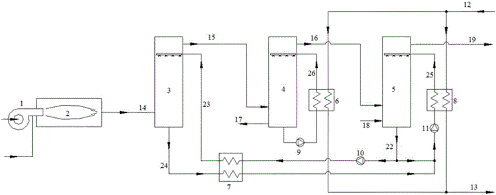
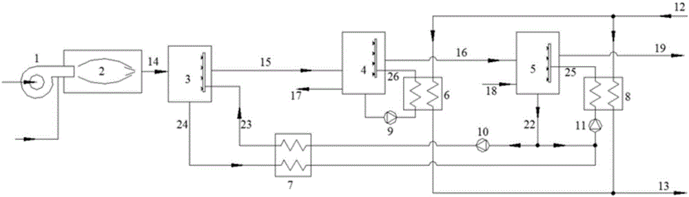
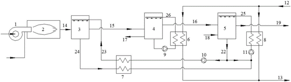
[0030] The present invention will be described in detail below in conjunction with the accompanying drawings and embodiments.

[0031] like figure 1 As shown, the present invention mainly consists of burner 1, combustion chamber 2, generator 3, condenser 4, absorber 5, water-water heat exchanger 6, solution-solution heat exchanger 7, solution-water heat exchanger 8 , condensate spray pump 9, solution circulation pump 10, solution spray pump 11, hot water return pipe 12, hot water supply pipe 13 and other connecting pipelines. Among them, the burner 1 is connected to the combustion chamber 2, the flue gas outlet of the combustion chamber 2 is connected to the flue gas inlet of the generator 3, the flue gas outlet of the generator 3 is connected to the flue gas inlet of the condenser 4, and the flue gas inlet of the condenser 4 The gas outlet is connected with the flue gas inlet of the absorber 5 to form a flue gas heat exchange path. Simultaneously, the concentrated solution ...


PUM


Abstract

The invention relates to a flue gas waste heat recovery unit which comprises a flue gas unit, a generator unit, a condenser unit, an absorber unit, a water return pipe and a water supply pipe. The flue gas unit is sequentially connected with the generator unit, the condenser unit and the absorber unit to form a flue gas heat exchanging path; the outlet of the generator unit is connected with the inlet of a solution-to-solution heat exchanger, the outlet of the absorber unit is divided into two paths: one path is merged with the outlet of the solution-to-solution heat exchanger to be connected with the inlet of a solution-to-water heat exchanger through a solution spray pump, the outlet of the solution-to-water heat exchanger is connected with a solution spray mechanism in the absorber unit, the other path is connected with the inlet of a solution-to-solution heat exchanger through a solution circulating pump, and the outlet of the solution-to-solution heat exchanger is connected with a dilute solution spray mechanism through the generator unit so as to form a solution heat exchanging and circulating loop; the outlet of the condenser unit is connected with the inlet of a water-to-water heat exchanger through a condense water spray pump, the outlet of the water-to-water heat exchanger is connected with a condense water spray mechanism through the condenser unit to form a condense water heat exchanging and circulating loop; the water return pipe is connected with a water-to-water heat exchanger unit and the inlet of a solution-to-water heat exchanger, and the water supply pipe is connected with the water-to-water heat exchanger and the inlet of the solution-to-water heat exchanger.

Description

technical field [0001] The invention relates to a heat supply device, in particular to a flue gas waste heat recovery device capable of recovering water vapor and heat in wet flue gas formed by burning natural gas, oil and other fuels. Background technique [0002] Fuels such as natural gas and oil have a high hydrogen content, so the flue gas emitted after combustion contains a large amount of water vapor. For example, in the flue gas of a natural gas boiler, the volume component of water vapor is close to 20%, which is the main carrier of the heat of the flue gas. According to statistics per 1Nm 3 Natural gas can produce 1.55kg of water vapor, and the latent heat is about 3600kJ / Nm 3 , accounting for about 10% of the low calorific value of natural gas. Therefore, the recovery of this part of water vapor and its heat (mainly latent heat) is economically meaningful. [0003] The invention patent with the publication number CN1414288 discloses a heat supply device for rec...

Claims


Application Information

Patent Timeline
Patent Type & Authority Patents(China)
IPC IPC(8): F24H7/02F24H8/00
CPCY02B30/00
Inventor 付林张世钢齐心唐道轲刘华吴彦廷
Owner TSINGHUA UNIV
Why Eureka
Try Eureka