Virtual time inversion-based sound emission passive imaging method and apparatus thereof

A technology of virtual time reversal and imaging method, which is applied in the direction of material analysis using acoustic wave emission technology, can solve the problems of large amount of calculation and complex implementation process, and achieves low dependence, easy implementation, high precision and fast imaging positioning. Effect

Active Publication Date: 2014-12-03
BEIJING AERONAUTIC SCI & TECH RES INST OF COMAC +1
View PDF3 Cites 13 Cited by
  • Summary
  • Abstract
  • Description
  • Claims
  • Application Information

AI Technical Summary

Problems solved by technology

The first method uses the time-reversed signal reconstruction process to locate the source of the acoustic emission, but before positioning, a large number of experiments must be carried out to measure the transfer function of each point of the measured structure, and the implementation process is complicated; the second method uses time-reversed focusing Imaging realizes positioning. In imaging, it is necessary to perform time-reversal focusing processing on all acoustic emission signals for each pixel point, which requires a large amount of calculation.

Method used


Image

  • Virtual time inversion-based sound emission passive imaging method and apparatus thereof
  • Virtual time inversion-based sound emission passive imaging method and apparatus thereof
  • Virtual time inversion-based sound emission passive imaging method and apparatus thereof

Examples


Embodiment 2

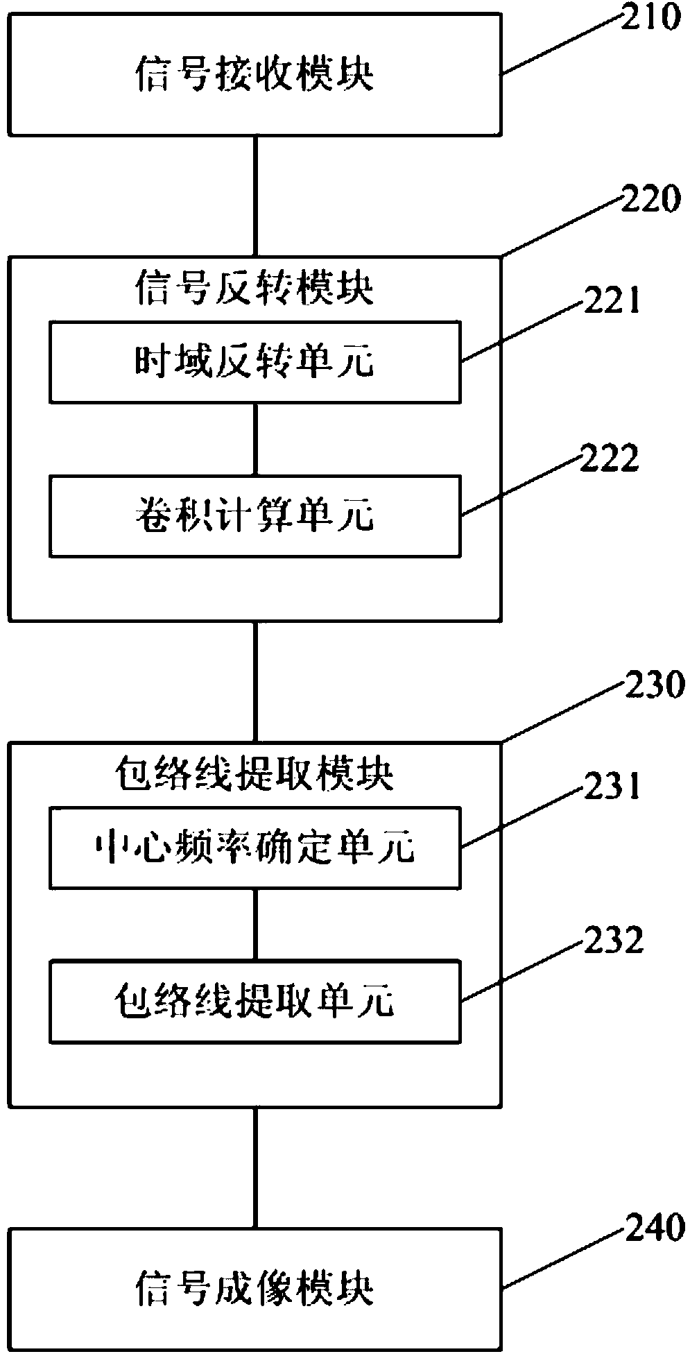
[0066] figure 2 A schematic structural diagram of an acoustic emission passive imaging device based on virtual time reversal provided by Embodiment 2 of the present invention, the device includes: a signal receiving module 210, a signal inversion module 220, an envelope extraction module 230 and a signal imaging module 240.

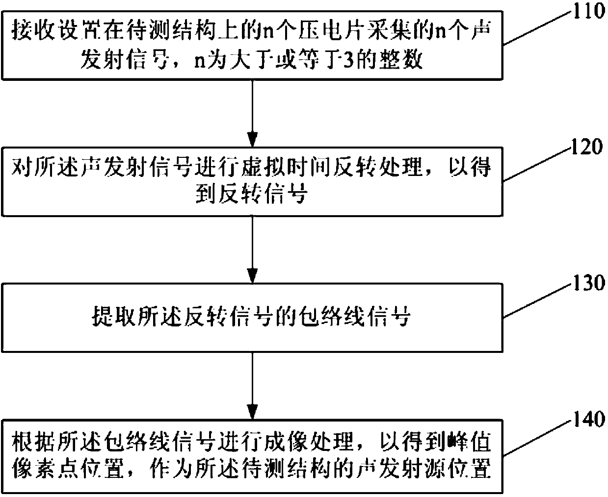
[0067] Wherein, the signal receiving module 210 is used to receive n acoustic emission signals collected by n piezoelectric sheets arranged on the structure to be tested, and n is an integer greater than or equal to 3; the signal inversion module 220 is used to The signal is subjected to virtual time reversal processing to obtain an inverted signal; the envelope extraction module 230 is used to extract the envelope signal of the inverted signal; the signal imaging module 240 is used to perform imaging processing according to the envelope signal , to obtain the position of the peak pixel point as the position of the acoustic emission source of the struct...

Embodiment 3

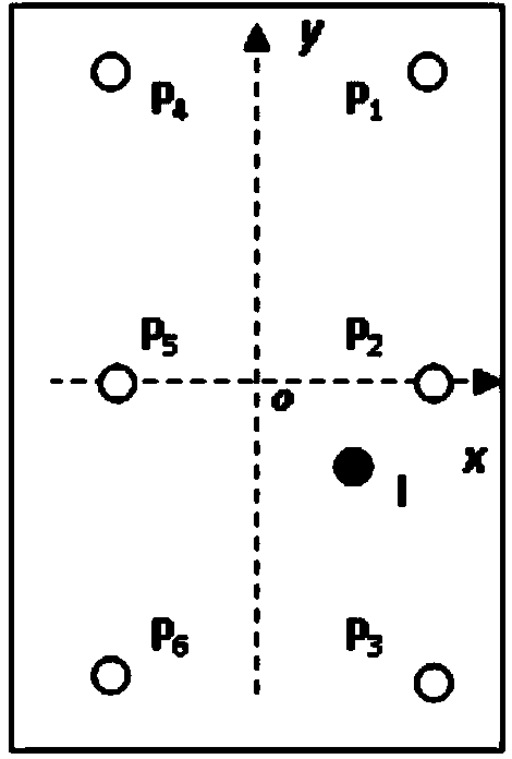
[0082] Referring to Fig. 3 (a) to (g), it is a specific schematic diagram of structural monitoring of a carbon fiber composite plate based on a virtual time-reversal acoustic emission passive imaging method provided by Embodiment 3 of the present invention. In this example, a carbon fiber composite plate is used as the structure to be tested, with a size of 600mm×300mm×2.25mm. The material of the carbon fiber layup is T300 / QY8911, the thickness is 0.125mm, and the layup sequence is [45 / 0 / -45 / 90 / 0 / 45 / 0 / -45 / 0] 2S , there are 6 piezoelectric sheets P arranged in the carbon fiber composite plate structure 1 ~P 6 The piezoelectric sensing array is formed, and the acoustic emission is to use the ordinary mechanical spring impact hammer to simulate the external impact of the structure to make the carbon fiber composite material plate generate an acoustic emission signal.

[0083] In this embodiment, based on the acoustic emission passive imaging method of virtual time-reversal pro...

Embodiment 4

[0103] Referring to FIG. 4( a ) to ( g ), it is a specific schematic diagram of structural monitoring of an aluminum plate material based on a virtual time-reversal acoustic emission passive imaging method provided by Embodiment 4 of the present invention. In this example, LY21 aluminum plate, which is prone to fatigue cracks, is used as the structure to be tested. The size is 2000mm×1200mm×2.25mm. Electrode P 1 ~P 9 The piezoelectric sensing array is composed, and the acoustic emission is the acoustic emission caused by the fatigue crack initiation or expansion in the aluminum plate simulated by breaking the lead.

[0104] This embodiment is based on a virtual time-reversal acoustic emission passive imaging method to perform fast and high-precision imaging and positioning of acoustic emission events caused by fatigue cracks in aluminum plates, without determining the arrival time of acoustic emission signals, and the calculation is simple.

[0105] Step 410, the piezoelectr...


PUM

PropertyMeasurementUnit
thicknessaaaaaaaaaa

Abstract

The invention discloses a virtual time inversion-based sound emission passive imaging method and an apparatus thereof. The method comprises the following steps: receiving n sound emission signals acquired by n piezoelectric patches arranged on a structure to be measured, wherein n is an integer not less than 3; carrying out virtual time reversion treatment on the sound emission signals to obtain reversed signals; extracting the envelope signals of the reversed signals; and imaging according to the envelope signals in order to obtain peak value pixel point positions used as the sound emission source positions of the structure to be measured. The virtual time inversion-based sound emission passive imaging method and the apparatus thereof allow single piezoelectric patch related undetermined absolute wave arrival time in the sound emission signals into a two piezoelectric patches related determined wave arrival time difference through the virtual time reversion treatment, is convenient to realize the highly-precious rapid imaging positioning, does not need the determination of the wave arrival time of the sound emission signals or the calibration of the performances of a piezoelectric transducer, and has low dependence on prior data.

Description

technical field [0001] The present invention relates to acoustic emission signal processing technology, in particular to an acoustic emission passive imaging method and device based on virtual time reversal. Background technique [0002] Acoustic emission, also known as stress wave emission, is a phenomenon in which a material or component is deformed or fractured by an external force, or the internal stress exceeds the yield limit and enters an irreversible plastic deformation stage, releasing strain energy in the form of a transient elastic wave. In the internal environment, the initiation and propagation of fatigue cracks in metal structures, fiber breakage in composite materials, interface damage, fiber pull-out, etc. will produce acoustic emissions, and in the external environment, the phenomenon that the structure is impacted to induce stress waves is also classified for acoustic emission. [0003] With the increasing requirements for structural safety and reliability...

Claims


Application Information

Patent Timeline
Patent Type & Authority Applications(China)
IPC IPC(8): G01N29/14
Inventor 蔡建卿新林高丽敏
Owner BEIJING AERONAUTIC SCI & TECH RES INST OF COMAC
Why Eureka
Try Eureka