Self-regulating error symbol integration robust control method for direct-drive motor system

A technology of direct drive motor and error sign, which is applied in the field of self-adjusting error sign integral robust control of direct drive motor system, can solve problems such as sliding mode surface flutter, difficult time acquisition, and deterioration of system tracking performance, so as to solve random performance, good tracking performance, and broad application prospects

Active Publication Date: 2014-12-03
NANJING UNIV OF SCI & TECH
View PDF2 Cites 23 Cited by
  • Summary
  • Abstract
  • Description
  • Claims
  • Application Information

AI Technical Summary

Problems solved by technology

However, the discontinuous controller designed by the classical sliding mode control is likely to cause the flutter problem of the sliding mode surface, thereby deteriorating the tracking performance of the system; in order to solve the problem of parameter uncertainty and uncertainty nonlinearity at the same time, the adaptive robust A control method is proposed, which can make the system obtain definite transient and steady-state performance under the condition that the two kinds of modeling uncertainties exist simultaneously. If the high-precision tracking performance is to be obtained, the feedback gain must be increased to reduce the Tracking error, however, excessive feedback gain will increase the bandwidth of the closed-loop system, which may excite the high-frequency dynamics of the system and destabilize the system; the error sign integral robust (RISE) control method can also effectively deal with modeling uncertainties problem, and can obtain continuous control input and asymptotic tracking performance
However, the value of the nonlinear robust gain in the controller designed by this control method needs to meet certain conditions, which are closely related to the upper bounds of the first-o

Method used


Image

  • Self-regulating error symbol integration robust control method for direct-drive motor system
  • Self-regulating error symbol integration robust control method for direct-drive motor system
  • Self-regulating error symbol integration robust control method for direct-drive motor system

Examples


Embodiment

[0100] In order to assess the performance of the designed controller, the following parameters are taken in the simulation to model the direct drive motor system:

[0101] Inertia load parameter m=0.02kg·m 2 ; Viscous friction coefficient B = 10N m s / rad; torque amplification factor k i =5N·m / V;

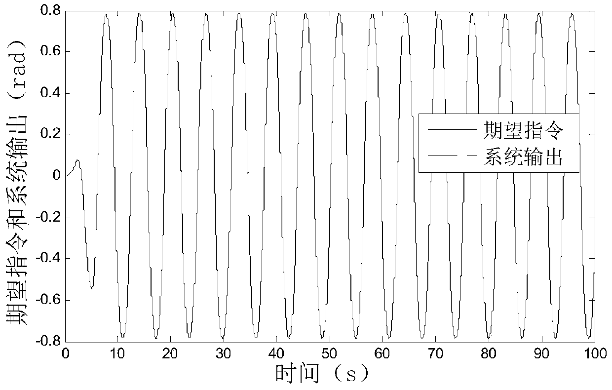
[0102] The desired instruction for a given system is x 1d =sin(t)[1-exp(-0.01t 3 )] (rad).

[0103] According to two different system working conditions, the simulation process is divided into two parts:

[0104] ①When the time-varying interference f(t)=10sint(N·m)

[0105] Take the following controller for comparison:

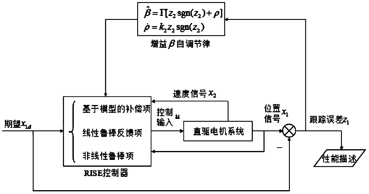
[0106] Self-regulating error sign integral robust (ARISE) controller: take the controller parameter k 1 =10,k 2 = 1,k r = 1; The self-regulating law gain Γ=50.

[0107] PID controller: The selection steps of PID controller parameters are as follows: first, under the condition of ignoring the nonlinear dynamics of the direct drive motor system, a set of co...


PUM


Abstract

The invention discloses a self-regulating error symbol integration robust control method for a direct-drive motor system. The method comprises the steps of establishing a mathematical model of the direct-drive motor system; designing a self-regulating error symbol integration robust controller; carrying out stability certification on the direct-drive motor system by using the Lyapunov stability theory, and acquiring a result of the global asymptotic stability of the system by using the Barbalat lemma. The self-regulating error symbol integration robust control method integrates the idea of self-adaptive control based on a traditional error symbol integration robust control method, and designs a controller gain self-regulating law so as to carry out on-line regulation on an integration robust gain value of the RISE controller. The self-regulating error symbol integration robust control method effectively solves problems of randomness, conservation, limitation and potential high-gain feedback in symbolic function gain regulation of a traditional RISE control method, and acquires better tracking performance.

Description

technical field [0001] The invention relates to the technical field of electromechanical servo control, in particular to a self-adjusting error sign integral robust control method of a direct drive motor system. Background technique [0002] In modern industrial production, many advanced mechanical equipment such as CNC machine tools, semiconductor processing equipment, and microelectronics manufacturing equipment widely use direct drive motor systems to ensure high-speed and high-precision processing. The direct drive motor (such as rotary and linear motor) system eliminates some mechanical transmission problems related to reduction gears, such as backlash, strong inertial loads, and structural flexibility. These nonlinear problems are the main factors affecting system performance. Existence will seriously deteriorate the control performance, so high-precision control performance can be obtained through advanced controller design for direct drive motor systems. However, du...

Claims


Application Information

Patent Timeline
IPC IPC(8): H02P21/00
Inventor 姚建勇邓文翔
Owner NANJING UNIV OF SCI & TECH
Why Eureka
Try Eureka