Manipulator internal-grab device based on worm-gear and crank-link transmission

A crank connecting rod and grabbing device technology, which is applied in the field of machinery, can solve problems such as not being able to meet the needs of economic development, and achieve the effects of reducing energy consumption, improving labor intensity of workers, and improving labor productivity and product quality

Inactive Publication Date: 2014-12-10
SUZHOU POLYTECHNIC INST OF AGRI
View PDF5 Cites 3 Cited by
  • Summary
  • Abstract
  • Description
  • Claims
  • Application Information

AI Technical Summary

Problems solved by technology

With the development of the economy and the improvement of automation requirements in all walks of life, robot technology has developed rapidly. Although various manipulator products have appeared, they still cannot meet the needs of economic development, especially in mechanical processing. A variety of manipulator products or end effectors are required to adapt and complete different tasks and operational requirements

Method used


Image

  • Manipulator internal-grab device based on worm-gear and crank-link transmission

Examples


Embodiment 1

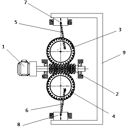
[0021] like figure 1 As shown, an inner gripping device of a manipulator based on the transmission of a worm gear and a crank connecting rod comprises an upper worm gear 3 and a lower worm gear 4, and the upper and lower crank connecting rods 5 and the lower crank connecting rod 6 are respectively hinged on the upper and lower worm gears, The end of the upper crank connecting rod 5 is fixedly connected with an upper grabbing head 7, and the end of the lower crank connecting rod 6 is fixedly connected with a lower grabbing head 8, and the upper and lower worm gears are driven by the same worm 2 that meshes with it, The two grabbing heads drive the crank connecting rod through the rotation of the upper and lower worm gears, so that the grabbing heads hold the workpiece tightly, and the worm 2 is driven by the deceleration motor 1 .

[0022] After the reduction motor 1 is driven, the output torque drives the worm 2 to rotate, the upper part of the worm 2 meshes with the upper wor...

Embodiment 2

[0025] The invention also discloses an inner gripping device of a manipulator based on the transmission of a worm worm gear and a crank connecting rod, which comprises three worm gears, a crank connecting rod is hinged on each worm gear, and the end of each crank connecting rod is fixedly connected with a gripping rod. The indenter, the three worm gears form an included angle of 120° with each other and are arranged along the peripheral surface of the worm, and the worm is driven by the worm, and the worm is driven by a deceleration motor.

[0026] The only difference between the second embodiment (not shown) and the first embodiment is that there are three worm gears arranged along the peripheral surface of the worm at an included angle of 120°, which facilitates the realization of three-point support for the cylindrical workpiece and the realization of fixation. , thereby expanding the scope of use of the inner grabbing device, the principle is the same as that of Embodiment ...

Embodiment 3

[0028] The invention also discloses an inner grasping device of a manipulator based on the transmission of a worm worm gear and a crank connecting rod. The indenter, the four worm gears form an included angle of 90° with each other and are arranged along the peripheral surface of the worm, and the worm is driven by the worm, and the worm is driven by a deceleration motor.

[0029] The only difference between this embodiment 3 (not shown) and the first embodiment is that there are four worm gears arranged along the peripheral surface of the worm with an included angle of 90° to each other, which is convenient to realize four-point support and fixation for larger workpieces. Thus, the scope of use and the fixing effect of the inner grabbing device are expanded, and the principle is the same as that of Embodiment 1, and will not be repeated here.

[0030] To sum up, the present invention provides an inner grasping device of a manipulator based on the transmission of a worm worm g...


PUM


Abstract

The invention discloses a manipulator internal-grab device based on worm-gear and crank-link transmission. The manipulator internal-grab device is characterized by comprising at least two gears; each gear is hinged with a crank link, a grab press head is fixedly connected to the tail end of each crank link and drives the same under rotation of the corresponding gear so as to support a workpiece tightly, and each gear is driven by one worm meshing with the same. Through second series-connection boosting of the worm-gear and crank-link transmission, high boost ratio is acquired, boosting effect is obvious, labor productivity and product quality can be improved and labor intensity of workers can be reduced. According to the nonlinear characteristic between the output force and the output displacement of a crank-link mechanism, the grab press heads are fed rapidly on the condition of large pressure angle, and the grab force is increased rapidly on the condition of small pressure angle.

Description

technical field [0001] The invention discloses an internal grasping device of a manipulator based on the transmission of a worm gear and a crank connecting rod, which belongs to the technical field of machinery. Background technique [0002] In modern industry, the mechanization and automation of the production process has become a prominent theme. The automation of continuous production processes such as chemical industry has been basically solved, while in the machinery industry, production such as processing and assembly is discontinuous, especially the handling of materials for domestic mechanical processing is still carried out manually or by special planes, which is relatively simple in products It is very suitable when the production capacity is not high, but with the progress of society and the development of technology, the use of manual or special plane loading and unloading has exposed many deficiencies and weaknesses, such as: (1) The special plane is complex in...

Claims


Application Information

Patent Timeline
Patent Type & Authority Applications(China)
IPC IPC(8): B25J15/08
Inventor 夏春风过琦芳
Owner SUZHOU POLYTECHNIC INST OF AGRI
Why Eureka
Try Eureka