
Rainwater and sewage flow converging and intercepting device

A technology for intercepting devices and confluence of rain and sewage, applied to water supply devices, waterway systems, drainage structures, etc., can solve problems such as urban waterlogging, river backflow, short-term pollution of water bodies, etc., to solve leakage problems, solve backflow, and prevent secondary The effect of secondary pollution

Inactive Publication Date: 2014-12-10
HEBEI AGRICULTURAL UNIV.
View PDF6 Cites 8 Cited by
  • Summary
  • Abstract
  • Description
  • Claims
  • Application Information

AI Technical Summary

Problems solved by technology

It is widely used in the sewage reconstruction of old urban areas. This transformation method has a series of advantages such as strong operability, small investment and quick results, convenient construction, and little impact on nearby residents during the construction process. However, this transformation method is due to During the rainy season, a large amount of rainwater will enter the interceptor, which will inevitably have a certain impact on the normal operation of the sewage pipe network and sewage treatment plant. After the renovation, the river water was poured back into the sewage pipe network, and some areas even aggravated the occurrence of urban waterlogging after the renovation.
If the above-mentioned problems cannot be solved well, not only will the completed sewage collection and treatment system not be able to fully play its due role, the investment benefit and social benefit will be reduced, but it will also bring certain problems to the normal production and life of the masses. Impact

Method used


Image

  • Rainwater and sewage flow converging and intercepting device
  • Rainwater and sewage flow converging and intercepting device
  • Rainwater and sewage flow converging and intercepting device

Examples


Embodiment Construction

[0022] Various embodiments of the invention will be described in more detail below with reference to the accompanying drawings. In the various drawings, the same elements are denoted by the same or similar reference numerals. For the sake of clarity, various parts in the drawings have not been drawn to scale.

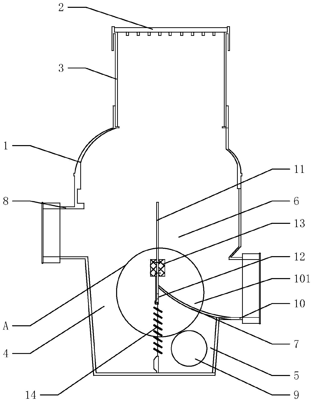
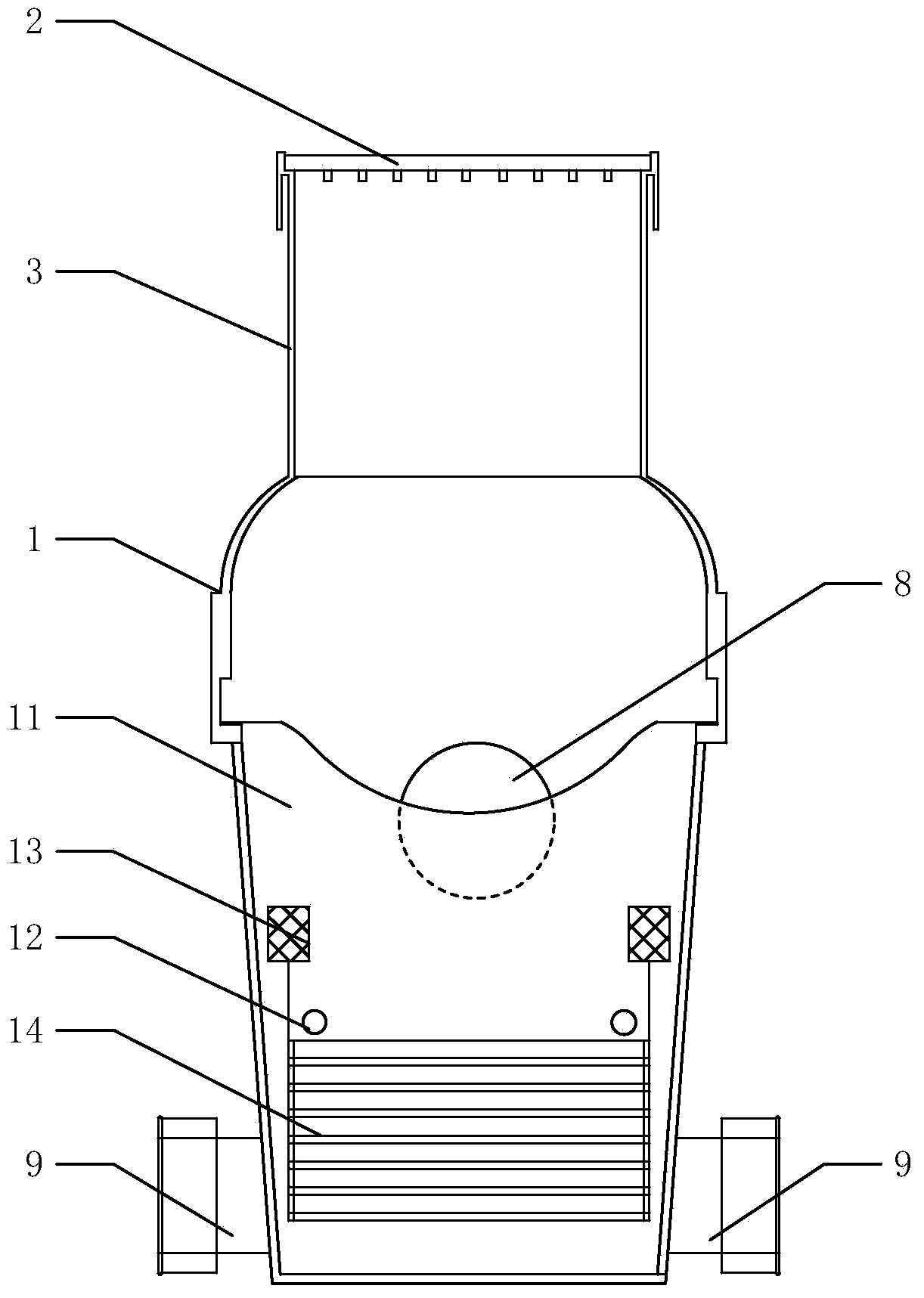
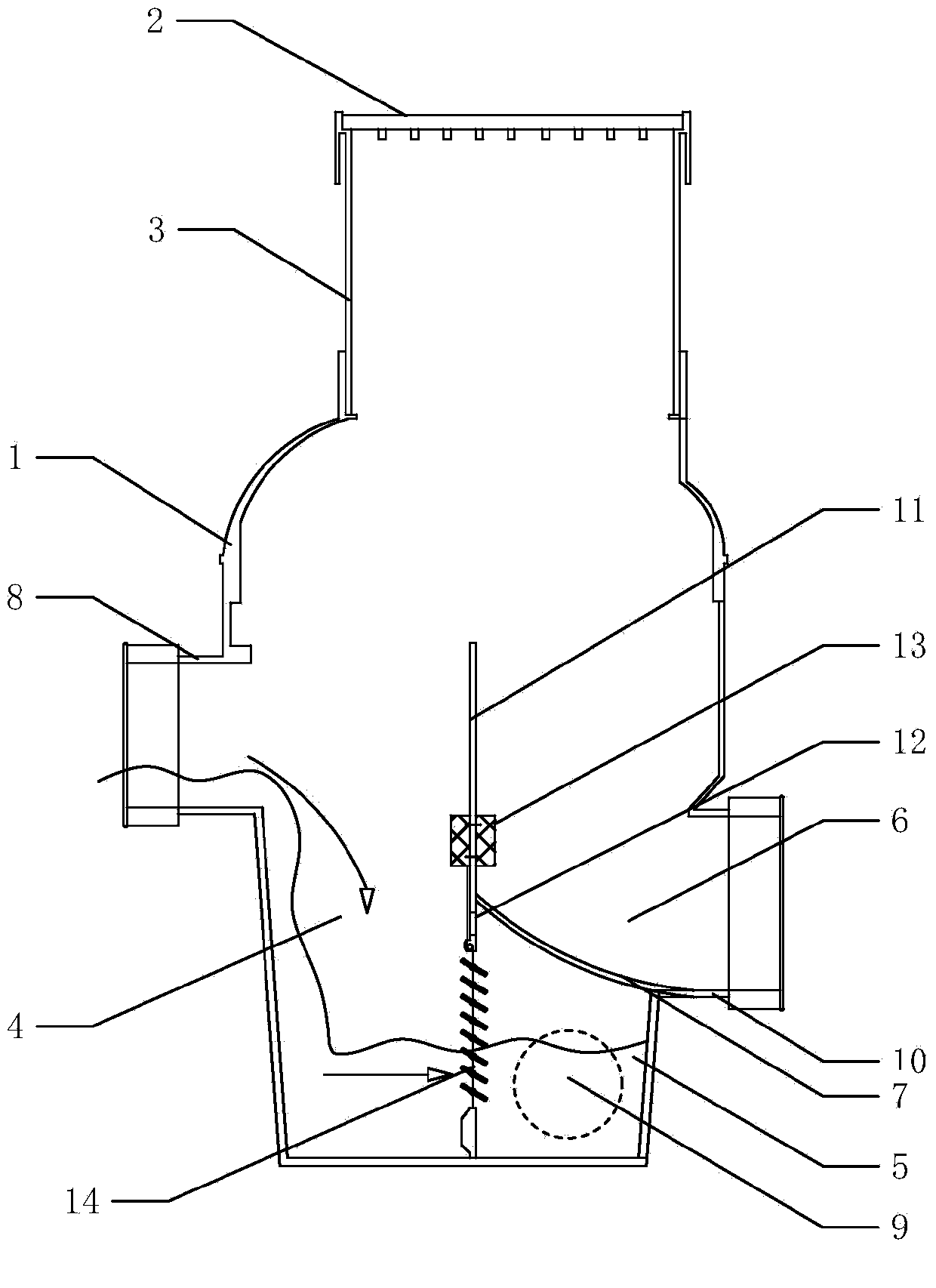
[0023] Such as figure 1 As shown, the rain and sewage confluence and interception device provided by the present invention includes a well body 1, a well cover 2, an inspection port 3, a water inlet chamber 4, a drainage chamber 5, an overflow chamber 6, a separation plate 7, a confluence pipe 8, an interception pipe 9, Overflow pipe 10, overflow weir 11, weep hole 12, float 13 and shutter valve 14. The well body 1 in the rain-sewage confluence interception device of the present invention is formed by integrated injection molding of polymer materials, which avoids the leakage problem of traditional "brick wells" and improves production efficiency. An inspection openi...


PUM


Abstract

The invention relates to a rainwater and sewage flow converging and intercepting device. The device is characterized by comprising a well body, an isolation plate, an overflow weir and a louvered valve. The well body is made of high molecular material in an integrated injection molding mode. A flow converging tube, an overflow tube and a flow intercepting tube are arranged on the well body. The interior of the well body is divided into a water inlet cavity, a water drainage cavity and an overflow cavity through the overflow weir, the louvered valve and the isolation plate. The flow converging tube is communicated with the water inlet cavity, the overflow tube is communicated with the overflow cavity, and the intercepting tube is communicated with the water drainage cavity. According to the rainwater and sewage flow converging and intercepting device, the well body is made of the high molecular material in the integrated injection molding mode, so that the leakage problem of a traditional bricked well is solved, and secondary pollution is eradicated; through reasonably arranging the water inlet cavity, the water drainage cavity and the overflow cavity, the device achieves rainwater and sewage flow converging and intercepting, and meanwhile the problem that external water bodies flow backward is solved.

Description

technical field [0001] The invention relates to the technical field of sewage treatment, in particular to a rain-sewage confluence interception device. Background technique [0002] With the development of the industrial economy and the discharge of waste water in people's daily life, the rivers in many cities have been seriously polluted, and the problem of waterlogging in cities has become increasingly serious. This problem is universal across the country. Based on my country's national conditions and the status quo of each city, except for some emerging cities (such as Shenzhen and Zhuhai), the old urban areas of most cities are built according to the confluence system, and it is difficult to change the status quo in a short period of time, so in the implementation It is difficult to completely divert rain and sewage in the whole area during sewage renovation, and it is inevitable to retain the combined system of rain and sewage in some areas. The interception renovation i...

Claims


Application Information

Patent Timeline
Patent Type & Authority Applications(China)
IPC IPC(8): E03F7/02E03F5/10
Inventor 刘俊良王佳伟冯利军李宏伟赵旭阳
Owner HEBEI AGRICULTURAL UNIV.
Learn More