High-temperature cyclone separation type three-waste co-combustion furnace

A technology of cyclone separation and co-combustion furnace, which is applied in the direction of incinerators, combustion methods, combustion types, etc., and can solve the problems of inability to return materials, waste energy, and reduce the combustion efficiency of co-combustion furnaces.

Inactive Publication Date: 2014-12-10
山东福源节能服务有限公司
View PDF0 Cites 5 Cited by
  • Summary
  • Abstract
  • Description
  • Claims
  • Application Information

AI Technical Summary

Problems solved by technology

Although this kind of blowing gas waste heat recovery device has solved many problems existing in the previous generations, and has also made many improvements, it has achieved good results, but most of the existing fluidized bed blowing gas recovery devices cannot carry out material return, boiling mixing, etc. After the high-temperature flue gas generated by the combustion furnace enters the built-in combined dust collector, the large particles of ash are separated from the flue gas and discharged out of the furnace. This part of the unburned ash is directly discharged to waste a lot of energy and reduce The combustion efficiency of the whole co-combustion furnace is improved

Method used


Image

  • High-temperature cyclone separation type three-waste co-combustion furnace
  • High-temperature cyclone separation type three-waste co-combustion furnace
  • High-temperature cyclone separation type three-waste co-combustion furnace

Examples


Embodiment Construction

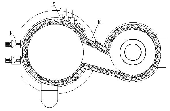
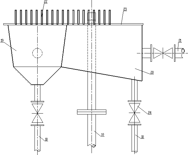
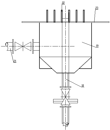
[0019] Such as Figure 1 to Figure 4 As shown, the high-temperature cyclone separation type three-waste mixed combustion furnace includes a combustion furnace 30 and a separator 9 communicating with the ash outlet 17 of the combustion furnace 30 . The combustion furnace 30 comprises a conical section arranged at the bottom and a cylindrical section arranged at the top. The diameter of the conical section gradually increases from bottom to top, and its maximum diameter is equal to the diameter of the cylindrical section; The diameter of the section is equal to the minimum diameter of the conical section of the combustion furnace 30. Two sets of spiral coal feeders 14 are installed on the side of the combustion section, and an air chamber 8 is installed on the bottom of the combustion section. An igniter 7 is installed on the side, and an air distribution device 6 is arranged horizontally between the combustion section and the air chamber. The combustion furnace 30 is provided ...


PUM


Abstract

The invention discloses a high-temperature cyclone separation type three-waste co-combustion furnace which comprises a combustion furnace and a separator communicated with an ash outlet of the combustion furnace. The combustion furnace is provided with a secondary air device, a combustor and a spiral coal feeder, a smoke outlet is formed in the upper portion of the separator, and a waste gas premixing device is installed on the side portion of the combustion furnace. An air distributing device is installed on the bottom of the combustion furnace, and an igniter and an air inlet are installed in the lower portion of the air distributing device. A central cylinder stretching downwards is arranged at the smoke outlet in the top of the separator, the lower end face of the central cylinder and the central line of the ash outlet are on the same horizontal plane, and a gas outlet pipe is connected to the smoke outlet in the top of the separator. A discharge port is formed in the bottom of the separator, the discharge port is communicated with a material return port in the lower portion of the combustion furnace through a material return pipe formed by sequentially connecting a first vertical section, a horizontal section, a second vertical section and an inclined section, the first vertical section is connected with the discharge port, the bottom end of the inclined section is connected with the material return port formed in the lower portion of the combustion furnace, and a material return device is arranged at the connecting position of the first vertical section and the horizontal section.

Description

technical field [0001] The invention relates to a high-temperature cyclone separation type three-waste mixed combustion furnace. Background technique [0002] The three-waste co-combustion furnace uses the combustion characteristics of the fluidized bed boiler and adopts the mode of blowing gas waste heat boiler to co-combust the waste slag, waste ash and waste gas generated by gas production (simultaneous combustion of the gas after hydrogen extraction) to generate high-temperature flue gas , after being dedusted by the combined dust collector, it enters the waste heat boiler arranged behind to generate steam waste heat utilization device. [0003] The earliest gas-generating and blowing gas recovery device has a combustion form of upward combustion and heat storage, which uses high-calorific-value syngas to burn and store heat, and then burns low-calorific-value gas-making and blowing gas to recover heat and by-product steam to protect the environment. The improved gas-ma...

Claims


Application Information

Patent Timeline
Patent Type & Authority Applications(China)
IPC IPC(8): F23G7/00
Inventor 刘钦王宪德
Owner 山东福源节能服务有限公司
Why Eureka
Try Eureka