
Backscattering cross section measuring method based on trace scanning two-dimensional near field imaging

A technology of backscattering and measurement methods, which is applied in the direction of radio wave reflection/re-radiation, radio wave measurement systems, and measurement devices. It can solve the problems of long circular scanning measurement time and affecting test efficiency, and achieves strong confidentiality. , the effect of high space utilization

Active Publication Date: 2014-12-10
INST OF ELECTRONICS CHINESE ACAD OF SCI
View PDF2 Cites 17 Cited by
  • Summary
  • Abstract
  • Description
  • Claims
  • Application Information

AI Technical Summary

Problems solved by technology

At present, the new measurement methods based on near-field imaging are all aimed at circular trace scanning. Obviously, under the requirement of sampling interval, the measurement time of circular trace scanning is longer, which will affect the test efficiency.

Method used


Image

  • Backscattering cross section measuring method based on trace scanning two-dimensional near field imaging
  • Backscattering cross section measuring method based on trace scanning two-dimensional near field imaging
  • Backscattering cross section measuring method based on trace scanning two-dimensional near field imaging

Examples


Embodiment Construction

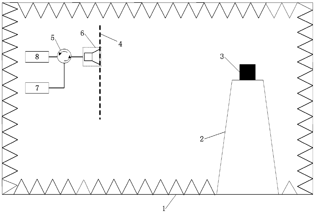
[0019] In order to make the object, technical solution and advantages of the present invention clearer, the present invention will be further described in detail below in conjunction with specific embodiments and with reference to the accompanying drawings. It should be noted that, in the drawings or descriptions of the specification, similar or identical parts all use the same figure numbers. Implementations not shown or described in the accompanying drawings are forms known to those of ordinary skill in the art. Additionally, while illustrations of parameters including particular values ​​may be provided herein, it should be understood that the parameters need not be exactly equal to the corresponding values, but rather may approximate the corresponding values ​​within acceptable error margins or design constraints.

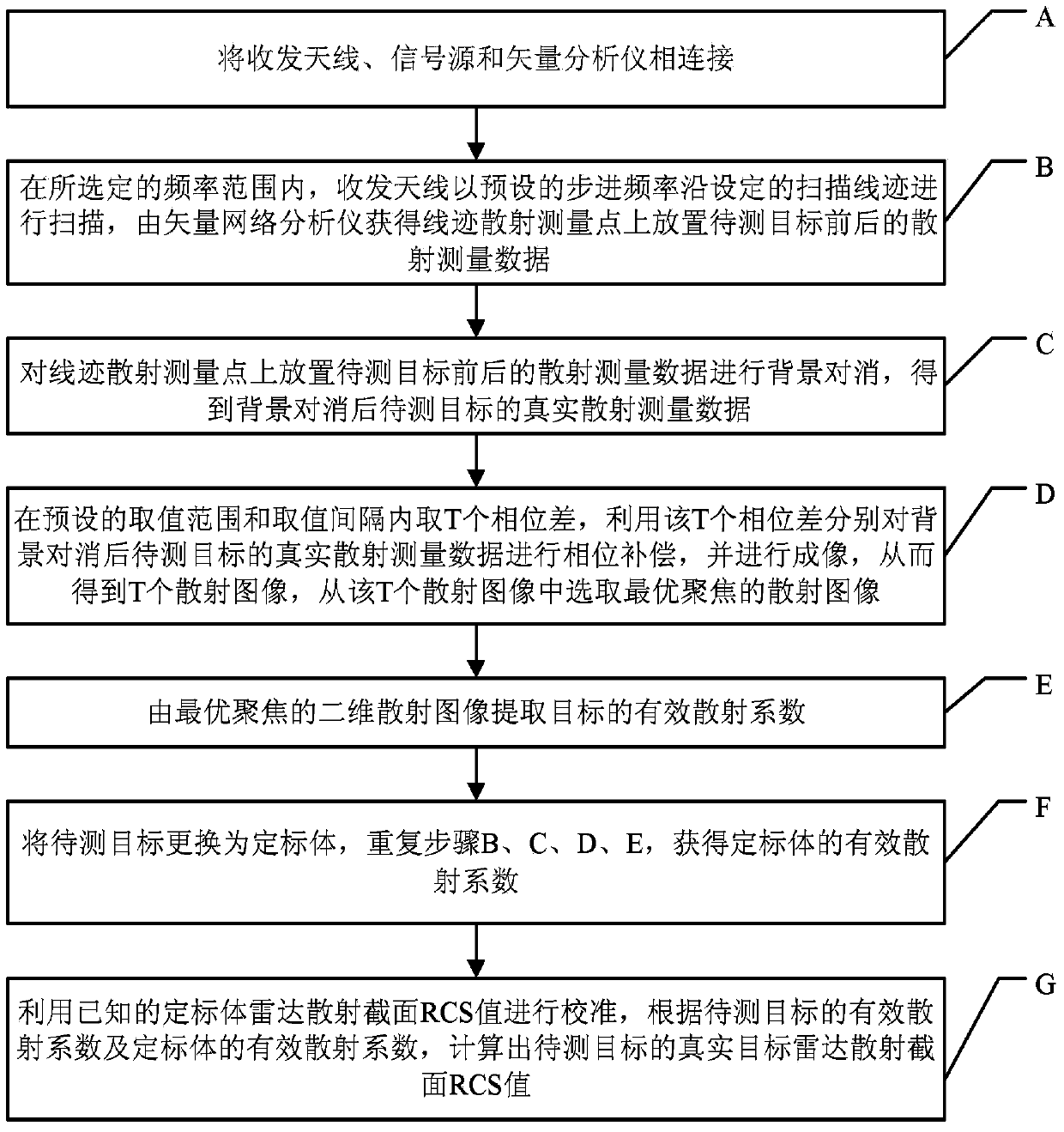
[0020] The backscattering cross-section measurement method based on two-dimensional near-field imaging of trace scanning according to the present invention, af...


PUM


Abstract

The invention provides a backscattering cross section measuring method based on trace scanning two-dimensional near field imaging. The backscattering cross section measuring method comprises the following steps: a transceiver antenna scans along a set scanning trace at a predetermined step frequency within a selected frequency range and a vector network analyzer obtains scattering measurement data before and after a target to be measured is placed in a trace scattering measurement point; background cancellation is performed on the scattering measurement data before and after a target to be measured is placed in a trace scattering measurement point; the optimally focused scattering image P is selected; the effective scattering coefficient as shown in the description of the target is extracted from the optimally focused two-dimensional scattering image P; the target to be measured is replaced by a calibration object and the effective scattering coefficient as shown in the description of the calibration object is obtained, and then the real target radar scattering cross-section (RCS) value of the target to be measured is calculated. The backscattering cross section measuring method based on trace scanning two-dimensional near field imaging is capable of obtaining either the scattering image of the target or the RCS value of the target, and further is capable of obtaining the electromagnetic scattering characteristics of the target more clearly, more specifically and more comprehensively.

Description

technical field [0001] The invention relates to the technical field of radar in the electronics industry, in particular to a backscattering cross-section measurement method based on trace scanning two-dimensional near-field imaging. Background technique [0002] Scattering cross-section testing techniques include external field testing, compact field testing, and near-field testing. The field test transceiver antenna is located in the far zone of the target to generate plane wave irradiation and only receive plane waves in one direction. Since the test distance needs to meet the far field conditions, and the target's stealth technology is becoming more and more advanced, the target scattering level is getting smaller and smaller. Therefore, there must be a large test site with a clean electromagnetic environment, and the influence of ground reflection needs to be eliminated or utilized, so it is becoming more and more difficult to construct a test environment under far-field...

Claims


Application Information

Patent Timeline
IPC IPC(8): G01S13/89G06F19/00G01S7/40G01S7/36
CPCG01S7/411G01S13/89
Inventor 吕晓德邢曙光丁赤飚林宽
Owner INST OF ELECTRONICS CHINESE ACAD OF SCI
Learn More