FPGA-based (field programmable gate array based) signal time difference measurement method and FPGA-based time-to-digital converter

A measurement method and time digital technology, applied to devices for measuring time intervals, electrical unknown time interval measurements, instruments, etc., can solve problems such as inaccurate measurement results

Active Publication Date: 2014-12-10
SHENZHEN KYLE OPTICS TECH CO LTD
View PDF4 Cites 12 Cited by
  • Summary
  • Abstract
  • Description
  • Claims
  • Application Information

AI Technical Summary

Problems solved by technology

[0006] The present invention aims at the technical problem in the prior art that the signal time difference is easily affected by environmental conditions such as tempera

Method used


Image

  • FPGA-based (field programmable gate array based) signal time difference measurement method and FPGA-based time-to-digital converter
  • FPGA-based (field programmable gate array based) signal time difference measurement method and FPGA-based time-to-digital converter
  • FPGA-based (field programmable gate array based) signal time difference measurement method and FPGA-based time-to-digital converter

Examples


Embodiment Construction

[0070] In order to facilitate the understanding of those skilled in the art, the following briefly introduces the clock management unit inside the FPGA chip.

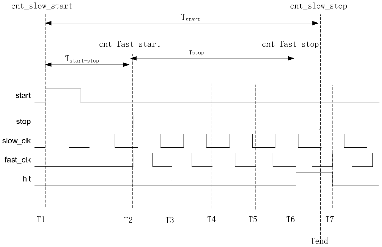
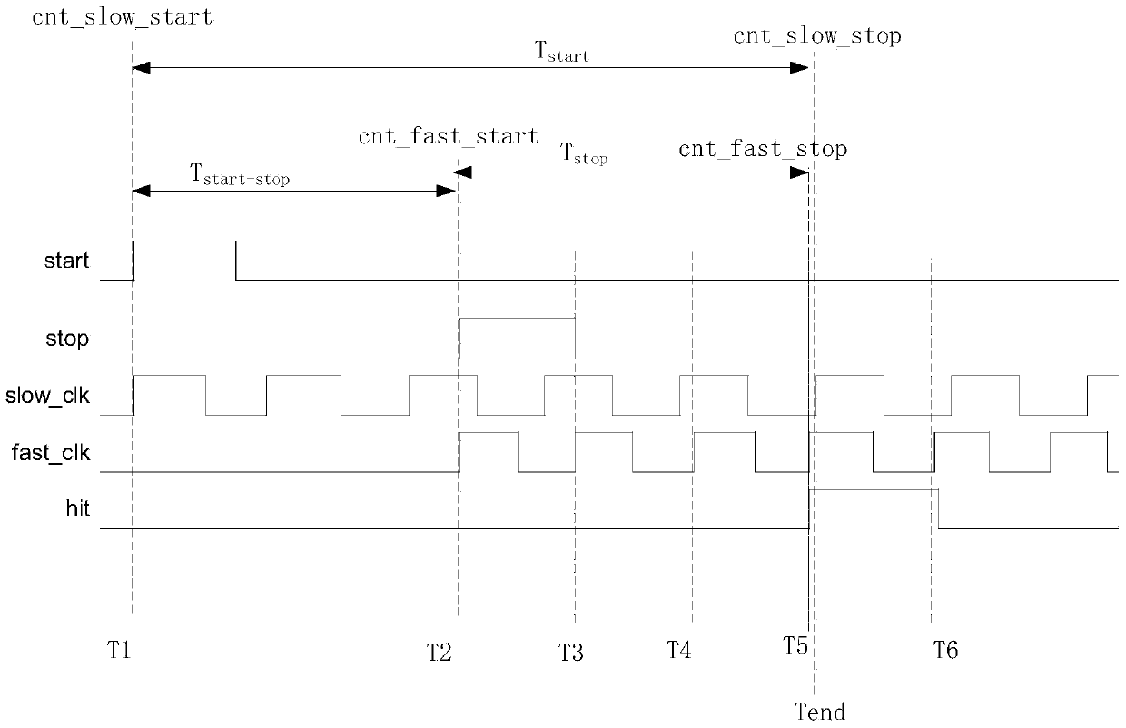
[0071] Since the clock management unit inside the FPGA chip has a dynamic phase adjustment capability to compensate for voltage and temperature offsets, it can be guaranteed not to be affected by temperature and voltage offsets, and the clock management unit has a frequency divider and a frequency multiplier, so The clock management unit can be used to form clock signals of various periods (frequency). However, not all clock signals with cycle (frequency) can be formed arbitrarily. For example, assuming that the FPGA external clock source is a 27MHz crystal oscillator, to realize a slow clock signal with a cycle of Ts=4.63ns (that is, a frequency of 216MHz) only needs to be It can be achieved by multiplying the frequency of the external clock source signal by 8 times; and to achieve a period of T f = 4.545ns (that is, ...


PUM


Abstract

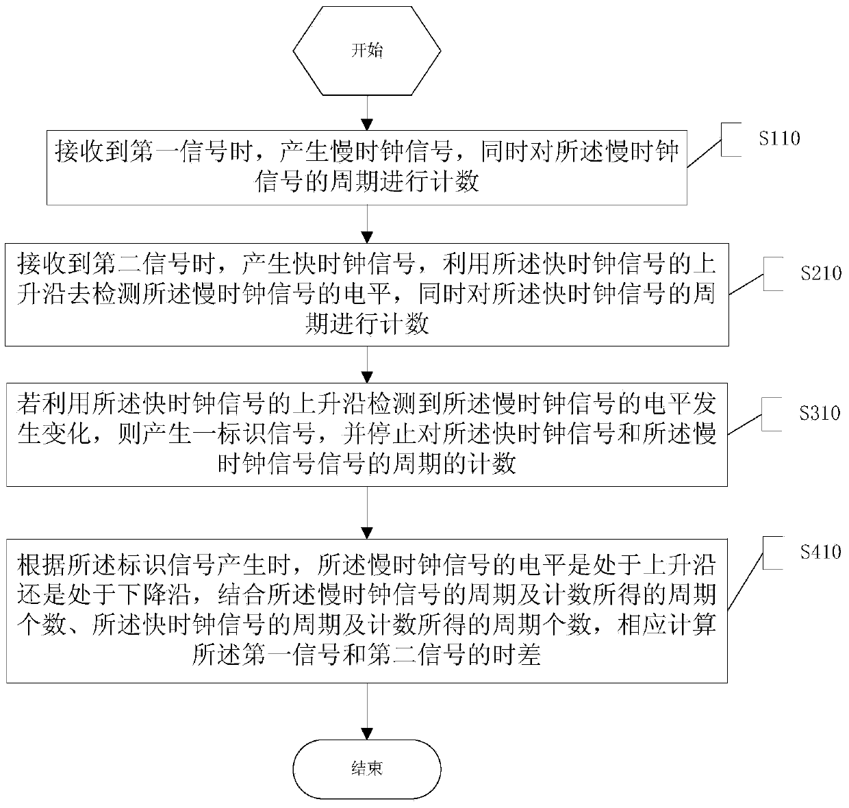
The invention relates to an FPGA-based (field programmable gate array based) signal time difference measurement method. The method includes the steps: on receiving a first signal, a slow clock signal is generated, and cycles of the slow clock signal are counted meanwhile; on receiving a second signal, a fast clock signal is generated, level of the slow clock signal is detected with a rising edge of the fast clock signal, and cycles of the fast clock signal are counted meanwhile; if changes in the level of the slow clock signal are detected with the rising edge of the fast clock signal, an identifier signal is generated, and counting the cycles of the fast clock signal and those of the slow clock signal is stopped; a time difference between the first signal and the second signal is correspondingly calculated, according to the fact that whether the level of the slow clock signal is on the rising edge or a falling edge when the identifier signal is generated and according to the cycles of the slow clock signal, the counted number of the cycles of the slow clock signal, the cycles of the fast clock signal and the counted number of the cycles of the fast clock signal. Compared with the prior art, the method has the advantage that time measurement accuracy is higher.

Description

technical field [0001] The invention relates to the field of signal time measurement, in particular to an FPGA-based signal time difference measurement method and a time-to-digital converter for measuring the time difference between two signals. Background technique [0002] Time is one of the fundamental properties of matter's existence and motion. Precise time, as the basic physical parameter of scientific research, scientific experiments and engineering technology, provides the necessary time-base coordinates for the measurement and quantitative research of all dynamical systems and time series processes. It is used in aerospace, deep space communication, address mapping Applied research fields such as navigation, communication and scientific metrology are particularly important. [0003] TDC (Time-to-Digital Converter, time-to-digital converter) is a commonly used electronic circuit for time interval measurement. Early TDC circuits usually consisted of discrete compone...

Claims


Application Information

Patent Timeline
IPC IPC(8): G04F10/04
Inventor 李亚锋张振军
Owner SHENZHEN KYLE OPTICS TECH CO LTD
Why Eureka
Try Eureka