A lathe for making paper machine vacuum roll

A vacuum roll and paper machine technology, applied in machine tool parts, manufacturing tools, tools for lathes, etc., can solve problems such as low dynamic balance, difficulty in returning and replacing tools, shortening the service life of vacuum rolls, etc., to eliminate low dynamic balance, The effect of advancing and retracting the knife is convenient and fast, improving production efficiency

Active Publication Date: 2015-07-29
无锡正杨造纸机械有限公司
View PDF4 Cites 0 Cited by
  • Summary
  • Abstract
  • Description
  • Claims
  • Application Information

AI Technical Summary

Problems solved by technology

Although this method can improve the deficiencies of the above two lathes, effectively improve the lathe performance, and improve the rigidity of the knife row when the lathe is lathed, it still cannot realize the one-time clamping of the inner circumference of the drum, the two ends, and the two ends. After the turning process is completed, the problems caused by the two times of clamping cannot be solved. It is also extremely difficult to return and replace the knife, and it is easy to cause the knife to jump and strain the inner wall of the drum after the turning process is completed.
[0007] To sum up, the existing turning equipment requires multiple clamping to complete the turning of the cylinder, which cannot ensure the high precision requirements of large diameter, long rollers, and high-speed operation of the vacuum roller. It is difficult to ensure that the end face A and The end face B is concentric and parallel; it is difficult to ensure that the spigot A cylinder is perpendicular to the end face B; the spigot B cylinder is perpendicular to the end face A; the spigot A cylinder, the spigot B cylinder and the inner cylinder of the drum are completely coaxial
After loading the shaft head at both ends of the drum, the low dynamic balance caused by the poor coaxiality of the drum and the shaft head will cause jumping of the whole roll and resonance at high speed, which greatly shortens the service life of the vacuum roll and even makes it unusable

Method used


Image

  • A lathe for making paper machine vacuum roll
  • A lathe for making paper machine vacuum roll
  • A lathe for making paper machine vacuum roll

Examples


Embodiment Construction

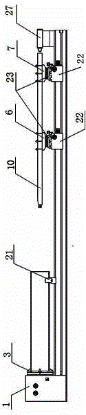
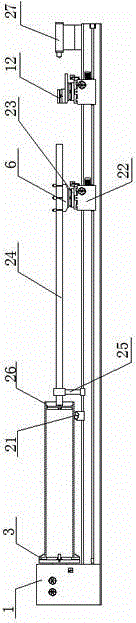
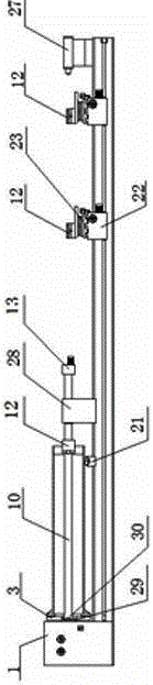
[0017] Such as Figure 4 Shown is a structural diagram of the present invention, a lathe for making a paper machine vacuum roll, which specifically includes the following structure: headstock 1, main shaft 2, chuck 3, first lathe bed 4, second lathe bed Body 5, first knife rack 6, second knife rack 7, first knife rack carriage 8, second knife rack carriage 9, knife rack 10, guide rail 11, knife rack holder 12, knife rack Tool rest feeding device 13 and workpiece center bracket 14; described main shaft 2 and chuck 3 are hollow structures, main shaft 2 is placed in headstock 1, and headstock 1, main shaft 2 and chuck 3 are placed in the lathe In the middle; the first knife rack 6 is placed above the first lathe bed 4, the second knife bank 7 is placed above the second lathe bed 5, and the workpiece center bracket 14 is placed above the second lathe bed 5; The above-mentioned first knife rack dragging plate 8 is placed above the first knife rack 6, and the second knife rack drag...


PUM

PropertyMeasurementUnit
surface roughnessaaaaaaaaaa

Abstract

The invention discloses a lathe for manufacturing a suction roll drum of a paper machine. The lathe for manufacturing the suction roll drum of the paper machine is provided with a lathe head, a main shaft, a chuck, two cutter row frames, a cutter row, cutter row cutter rests and a cutter row cutter rest feeding device and is further provided with two lathe beds, two cutter row supporting plates, a guide rail and a workpiece central supporting frame. The main shaft and the chuck are both of a hollow structure. The main shaft is arranged in the lathe head. The lathe head and the chuck are arranged in the middle of the lathe. The two cutter row frames are arranged on the two lathe beds respectively. The workpiece central supporting frame is arranged on the second lathe bed. The two cutter row supporting plates are arranged above the two cutter frames. One end of the cutter row is erected on the first cutter row frame supporting plate, and the other end of the cutter row penetrates through the portion, located in the lathe head, of the main shaft to be erected on the second cutter row frame supporting plate. The cutter row cutter rests, the cutter row cutter rest feeding device and the guide rail are all arranged at the same end of the cutter row. By the adoption of the lathe for manufacturing the suction roll drum of the paper machine, one-off clamping is achieved, and all the steps of manufacturing of the suction roll drum through the lathe can be completed; cutter feeding and retracting are convenient and rapid, the production efficiency is improved, and the high-precision requirement of suction roll drum manufacturing is met.

Description

technical field [0001] The invention relates to a papermaking machine, in particular to a lathe of a papermaking machine, in particular to a lathe for making a vacuum roll of a papermaking machine. Background technique [0002] With the rapid development of papermaking technology, people have higher and higher requirements for papermaking width and speed. In the 1980s and 1990s, the papermaking width of paper machines in my country was generally 1760mm and 2400mm, and the speed was 150m and 300m. 1000m / min, the annual output of the paper machine can be as high as 300,000 tons, and has been developing to foreign speeds of 1500, 1800, 2200...2800m / min, and the efficiency of papermaking has been greatly improved. The improvement of papermaking efficiency is directly related to the production accuracy of the vacuum roll of the paper machine. The higher the precision of the vacuum roll production, the more it can meet the paper web and speed requirements of papermaking. If you w...

Claims


Application Information

Patent Timeline
Patent Type & Authority Patents(China)
IPC IPC(8): B23B5/08
CPCB23B5/08B23B27/00B23Q3/00B23Q5/40B23Q2240/007
Inventor 杨碧荣杨远圆
Owner 无锡正杨造纸机械有限公司
Why Eureka
Try Eureka