Trailing edge flap-type smart rotor blade

A technology of trailing edge flaps and rotor blades, which is applied in the field of helicopter component design, can solve problems such as large gaps, unreasonable partial design, and no complete and effective solution for the integrated design of the drive system. Ease of placement

Active Publication Date: 2014-12-17
CHINA HELICOPTER RES & DEV INST
View PDF6 Cites 3 Cited by
  • Summary
  • Abstract
  • Description
  • Claims
  • Application Information

AI Technical Summary

Problems solved by technology

[0004] The design of ACF rotor blades in Europe, the United States and other countries is too dependent on material technology and process level. my country has a large gap in this regard, so it is impossible to realize foreign design schemes; domestic research on ACF blades focuses on the principle design of the

Method used


Image

  • Trailing edge flap-type smart rotor blade
  • Trailing edge flap-type smart rotor blade
  • Trailing edge flap-type smart rotor blade

Examples


Embodiment Construction

[0045] A trailing edge flap type intelligent rotor blade is characterized in that:

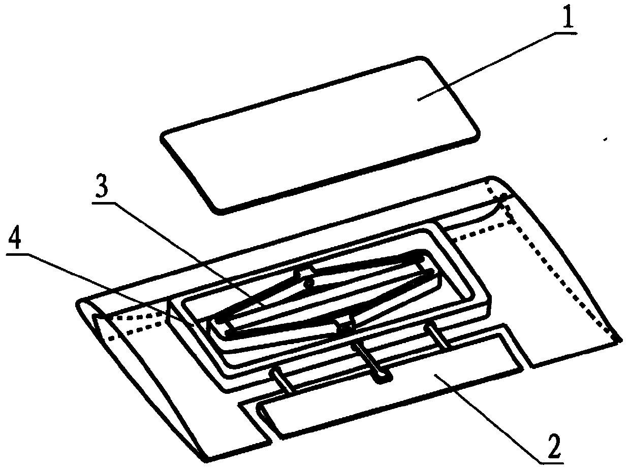
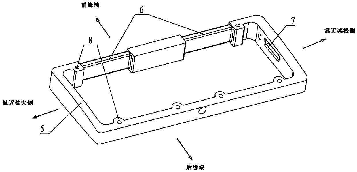
[0046] (1) The trailing edge flap type intelligent rotor blade includes the blade body, drive frame, actuator, and trailing edge flap, and each part is connected by binding, bonding, and bolt fastening;

[0047] (2) The drive frame is included in the blade skin, its upper and lower surfaces are parallel to the upper and lower airfoil surfaces, and the leading edge end face is pasted on the end face of the blade beam; grooves are made at both ends of the leading edge wall of the drive frame, and the beam belt is used to fit the groove Wrap the front edge wall of the drive frame on the leading edge beam of the blade; open a hole on the side wall of the drive frame close to the root of the blade, and wrap the middle beam of the blade through the hole and wrap it on the inner bolt; the drive frame is close to the tip of the blade. Blocking blocks made of glass fiber fabric cloth and carbon fiber f...


PUM


Abstract

The invention discloses a trailing edge flap-type smart rotor blade, belongs to the technique of design of helicopter parts, and relates to a smart rotor blade which is compact in structure and can meet the strength requirement. The trailing edge flap-type smart rotor blade is characterized in that a drive frame is located on the basis of the principle of invariable number of bundles of girder belts at the front edge; a flap-type datum line is utilized as a normal line of a front edge locating plane; a joint of the drive system in a composite material blade adopts any combination of three ways, namely front edge girder binding, middle girder pulling, and an end part top block; and a wing flap shaft is wrapped by using a chopped limiting block connected with skin. The invention proposes a design scheme of the trailing edge flap-type smart rotor blade under the precondition of not destroying the flap-type pneumatic surface. The blade adopting the scheme is reasonable in structure, and has an effective process program, the strength of the joint is ensured to the maximal extent, and the condition that the drive system can safely and stably work under various rotor test conditions.

Description

technical field [0001] The invention belongs to the design technology of helicopter components, in particular to a trailing edge flap type intelligent rotor blade. Background technique [0002] The working principle of the trailing edge flap type intelligent rotor is to use the aerodynamic force generated by the independent movement of the trailing edge flap to offset the vibration load of the blade. The research basis is to develop a pair of trailing edge flap type intelligent rotor blades. The so-called "trailing edge flap" refers to the independent lifting surface arranged on the trailing edge of the blade, which can perform fixed-axis deflection movement, which is similar to the rudder surface of a fixed-wing aircraft; "smart" refers to the use of The actuator, under the control of the adaptive program, drives the trailing edge flap to make a specific movement, thereby generating high-order aerodynamic forces to counteract the vibration of the blade. Compared with ordin...

Claims


Application Information

Patent Timeline
IPC IPC(8): B64C27/46B64C27/473
Inventor 邓旭东胡和平徐林周云孟微高乐彭敏刚
Owner CHINA HELICOPTER RES & DEV INST
Why Eureka
Try Eureka