Novel packaging machine for massive food

A new type of packaging and food technology, applied in packaging, transportation packaging, multiple packages, etc., can solve the problems of low packaging efficiency, pattern or pattern deviation, difficult positioning of packaging film, etc., to achieve beautiful packaging products and improve packaging. The effect of efficiency

Active Publication Date: 2014-12-17
SUZHOU MULTITECH AUTOMATION EQUIP CO LTD
View PDF7 Cites 4 Cited by
  • Summary
  • Abstract
  • Description
  • Claims
  • Application Information

AI Technical Summary

Problems solved by technology

[0005] 1. In the prior art, the packaging of bulk materials is to first cut the entire roll of film into a single film, and then the single film is packaged corresponding to a single material. This packaging method is to package a single material intermittently. The packaging process wastes time and the packaging efficiency is low
[0006] 2. In the packaging method of block materials in the prior art, the sheet film corresponds to the packaging of a single material, so it is difficult to locate the packaging film, and the pattern or pattern on the packaging film cannot be positioned at a specific position of the material, so that in the subsequ

Method used


Image

  • Novel packaging machine for massive food
  • Novel packaging machine for massive food
  • Novel packaging machine for massive food

Examples


Embodiment 1

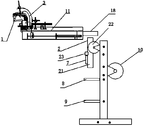
[0046] As a preferred embodiment of the present invention, with reference to the attached figure 1 , the invention includes

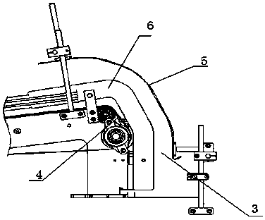
[0047] The material conveying mechanism 1, the tail end of the material conveying mechanism 1 is provided with a turning channel 3; the upper end of the bag turning channel 3 is arranged at the tail end of the material conveying mechanism 1, and the lower end of the bag turning channel 3 extends downward; the conveying device 11 is arranged on one side of the material conveying mechanism 1, and one end of the conveying device 11 is arranged below the bag turning channel 3; the other end of the conveying device 11 is provided with a receiving platform 18; The blanking bag forming device 2; the bag turning channel 3 includes a side baffle 6, a guide plate 4 and a guide baffle 5, the guide plate 4 is located at the tail end of the material conveying mechanism 1 and is inclined downward; the guide baffle The plate 5 is arranged above the guide plate 4, one...

Embodiment 2

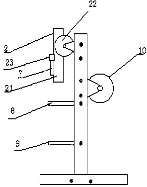
[0051] As another preferred embodiment of the present invention, with reference to the attached figure 1 and 2 , the invention includes

[0052] The material conveying mechanism 1, the tail end of the material conveying mechanism 1 is provided with a turning channel 3; the upper end of the bag turning channel 3 is arranged at the tail end of the material conveying mechanism 1, and the lower end of the bag turning channel 3 extends downward; the conveying device 11 is arranged on one side of the material conveying mechanism 1, and one end of the conveying device 11 is arranged below the bag turning channel 3; the other end of the conveying device 11 is provided with a receiving platform 18; The blanking bag forming device 2; the bag turning channel 3 includes a side baffle 6, a guide plate 4 and a guide baffle 5, the guide plate 4 is located at the tail end of the material conveying mechanism 1 and is inclined downward; the guide baffle The plate 5 is arranged above the guide...

Embodiment 3

[0058] As another preferred embodiment of the present invention, with reference to the attached figure 1 and 2 , the invention includes

[0059] The material conveying mechanism 1, the tail end of the material conveying mechanism 1 is provided with a turning channel 3; the upper end of the bag turning channel 3 is arranged at the tail end of the material conveying mechanism 1, and the lower end of the bag turning channel 3 extends downward; the conveying device 11 is arranged on one side of the material conveying mechanism 1, and one end of the conveying device 11 is arranged below the bag turning channel 3; the other end of the conveying device 11 is provided with a receiving platform 18; The blanking bag forming device 2; the bag turning channel 3 includes a side baffle 6, a guide plate 4 and a guide baffle 5, the guide plate 4 is located at the tail end of the material conveying mechanism 1 and is inclined downward; the guide baffle The plate 5 is arranged above the guide...


PUM


Abstract

The invention provides a novel packaging machine for massive food, and relates to the technical field of food packaging machines. A material is packaged in the film sending process, so the packaging efficiency is improved; in the packaging process, the positions of patterns on the packaging film can be well controlled, so that the patterns are packaged in the specific positions of the material, and thus the packaged tissue is more attractive, and the needs of daily life of people are met.

Description

technical field [0001] The invention relates to the technical field of food packaging machines, in particular to a novel packaging machine for block food. Background technique [0002] On February 22, 2006, the State Intellectual Property Office disclosed an invention patent with the publication number CN1736801A and the name "A Material Packaging Machinery". The feeding device and the packaging film forming and sealing device, the film feeding device includes a cutting film mechanism; the packaging film forming and sealing device includes a packaging film pallet arranged on the machine base, and the pallet is provided with shapes and sizes Material through-holes that match the materials to be packaged; and a packaging film former arranged above the material through-hole of the packaging film pallet; The operation direction of the clamping part and the material pushing part are perpendicular; and a group of packing hands on the bottom surface of the material between the pac...

Claims


Application Information

Patent Timeline
IPC IPC(8): B65B51/26B65B61/06B65B9/10B65B35/30
Inventor 张一帆
Owner SUZHOU MULTITECH AUTOMATION EQUIP CO LTD
Why Eureka
Try Eureka