
Mechanical arm positioning fetching method based on machine vision

A technology of machine vision and robotic arm, applied in the field of robotic arm, can solve the problems of high cost and poor real-time performance, and achieve the effect of improving accuracy, fast and flexible grasping, and ensuring accuracy

Active Publication Date: 2014-12-17
BEIJING JOINHOPE IMAGE TECH
View PDF2 Cites 49 Cited by
  • Summary
  • Abstract
  • Description
  • Claims
  • Application Information

AI Technical Summary

Problems solved by technology

[0010] The purpose of the present invention is to overcome the shortcomings of poor real-time performance and high cost in the existing mechanical arm grasping method, and provide a mechanical arm positioning and grasping method based on machine vision

Method used

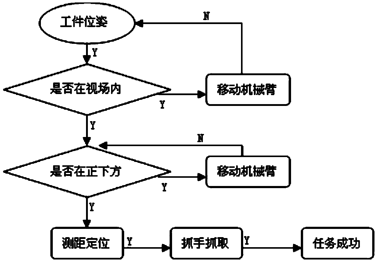
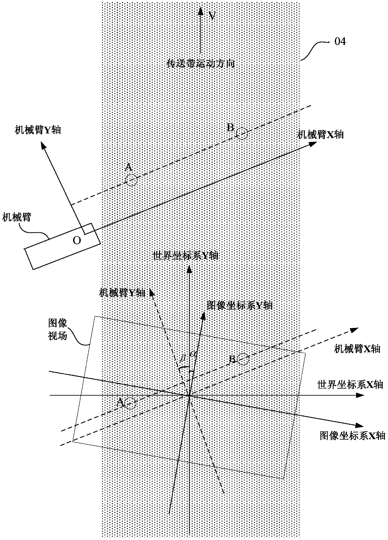

Image

  • Mechanical arm positioning fetching method based on machine vision
  • Mechanical arm positioning fetching method based on machine vision
  • Mechanical arm positioning fetching method based on machine vision

Examples


Embodiment Construction

[0050] The above and other technical features and advantages of the present invention will be further described below in conjunction with the accompanying drawings.

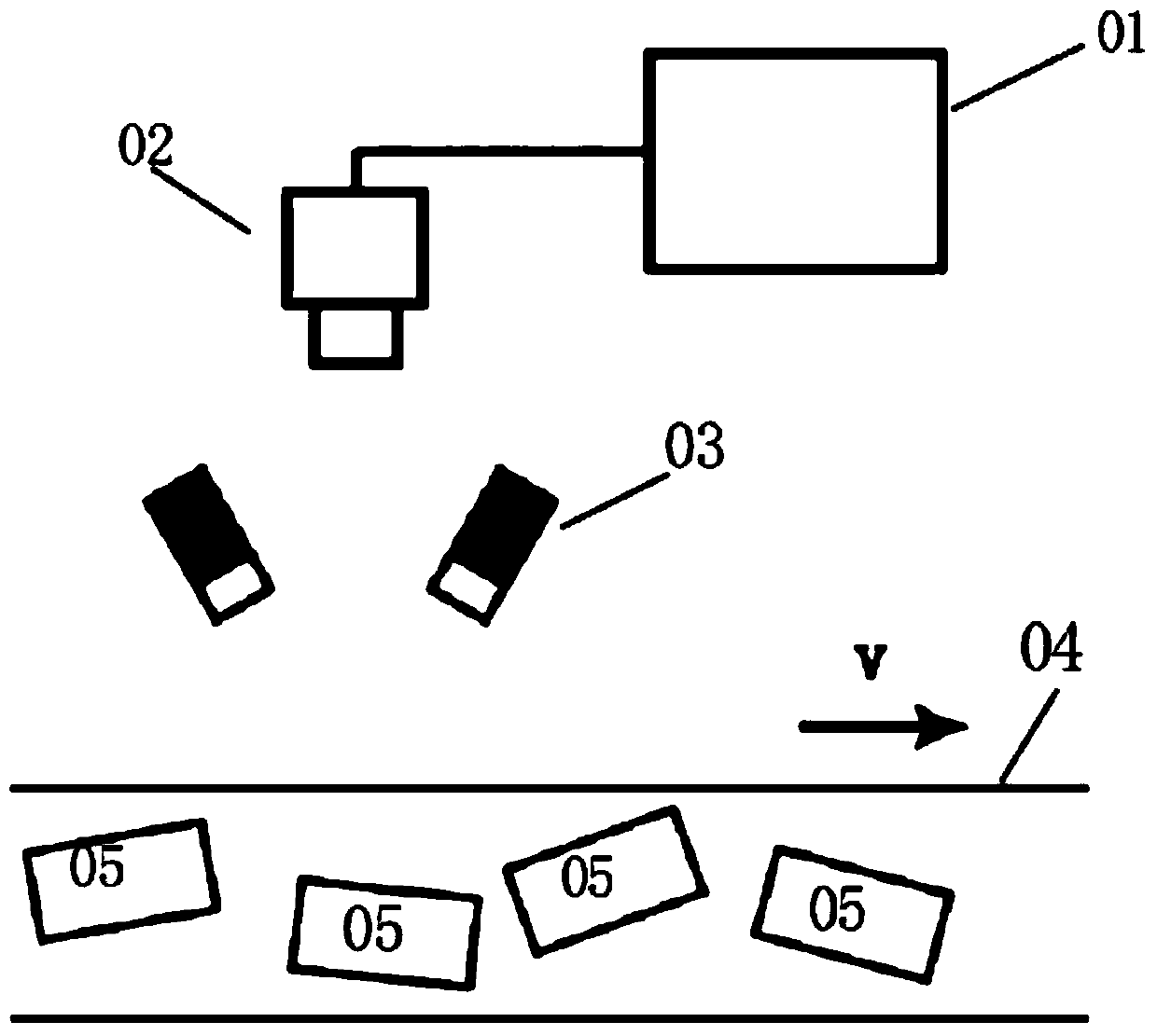
[0051] see figure 2 , is a schematic diagram of the position among the camera 02 , the conveyor belt 04 and the workpiece 05 in the present invention. The present invention connects the camera 02 and the mechanical arm (not shown in the figure) through the computer 01 to carry out information transmission and control. The present invention may include a plurality of mechanical arms, which are arranged beside the conveyor belt at certain intervals, and grasp the workpieces 05 scattered on the conveyor belt 04 under the control of the computer 01 . One of the advantages of the present invention is that only one camera 02 needs to be installed above the conveyor belt 04 , instead of having to equip each mechanical arm with a camera as in the prior art, which greatly reduces the production cost and facilitates larg...


PUM


Abstract

The invention discloses a mechanical arm positioning fetching method based on machine vision. The mechanical arm positioning fetching method comprises the following steps: S1) carrying out parameter calibration on a camera and a mechanical arm, establishing relationship between an image coordinate system and a conveyor belt coordinate system as well as between a mechanical arm coordinate system and the conveyor belt coordinate system; S2) identifying a target workpiece in the image, and calculating the centroid and the angle of deflection of the target workpiece; and S3) sending the centroid and the angle-of-deflection information, which are calculated in the step2), of the target workpiece to the mechanical arm, calculating a position coordinate of the target workpiece under a mechanical arm coordinate system to fetch the target workpiece. The invention exhibits a wide application range, and a great quantity of scattered workpieces can be quickly and accurately fetched under the condition that a production line is not changed, operation is flexible, and cost is saved.

Description

technical field [0001] The invention relates to the technical field of manipulators, in particular to a machine vision-based manipulator positioning and grasping method suitable for high-speed assembly line operations. Background technique [0002] Since the birth of the first robot in the world in the 1950s, robotics has experienced a slow process of development. Later, with the development of computer technology and microelectronics technology, machine vision appeared in the 1980s and developed rapidly in the 1990s. At this time, machine vision also extends from the field of scientific research to the field of application. [0003] In the process of modern industrial automation production, machine vision has been widely used, such as automatic detection of mechanical parts, intelligent control and automatic monitoring of production lines, automatic tracking and identification of moving targets, etc. However, the cooperation between machine vision and mechanical arms is st...

Claims


Application Information

Patent Timeline
Patent Type & Authority Applications(China)
IPC IPC(8): G06T7/20
Inventor 张友彬
Owner BEIJING JOINHOPE IMAGE TECH
Learn More