
PWM wave dead zone generating circuit

A technology for generating circuits and dead zones, applied to electrical components, output power conversion devices, etc., can solve the problems of high cost, poor repeatability, and many signal lines for PWM wave dead zone generation circuits, and achieve easy adjustment, improved accuracy, The effect of fewer transmission cables

Inactive Publication Date: 2014-12-17
SHANGHAI ADVANCED RES INST CHINESE ACADEMY OF SCI +1
View PDF7 Cites 1 Cited by
  • Summary
  • Abstract
  • Description
  • Claims
  • Application Information

AI Technical Summary

Problems solved by technology

[0010] In view of the shortcomings of the prior art described above, the purpose of the present invention is to provide a PWM wave dead zone generation circuit, which is used to solve the problem of high cost, poor repeatability, low precision, and many signal lines of the PWM wave dead zone generation circuit in the prior art. , large interference and other issues

Method used


Image

  • PWM wave dead zone generating circuit
  • PWM wave dead zone generating circuit

Examples


Embodiment Construction

[0036] Embodiments of the present invention are described below through specific examples, and those skilled in the art can easily understand other advantages and effects of the present invention from the content disclosed in this specification. The present invention can also be implemented or applied through other different specific implementation modes, and various modifications or changes can be made to the details in this specification based on different viewpoints and applications without departing from the spirit of the present invention.

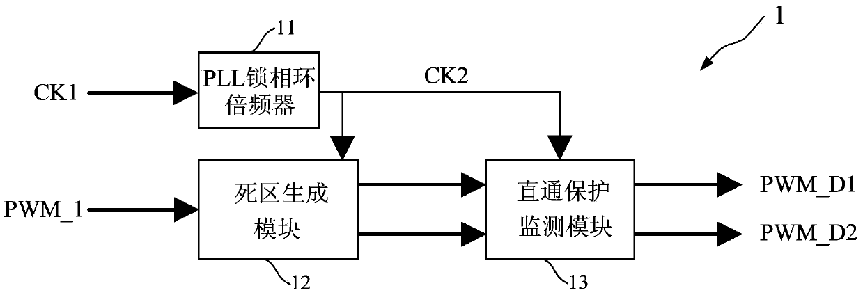
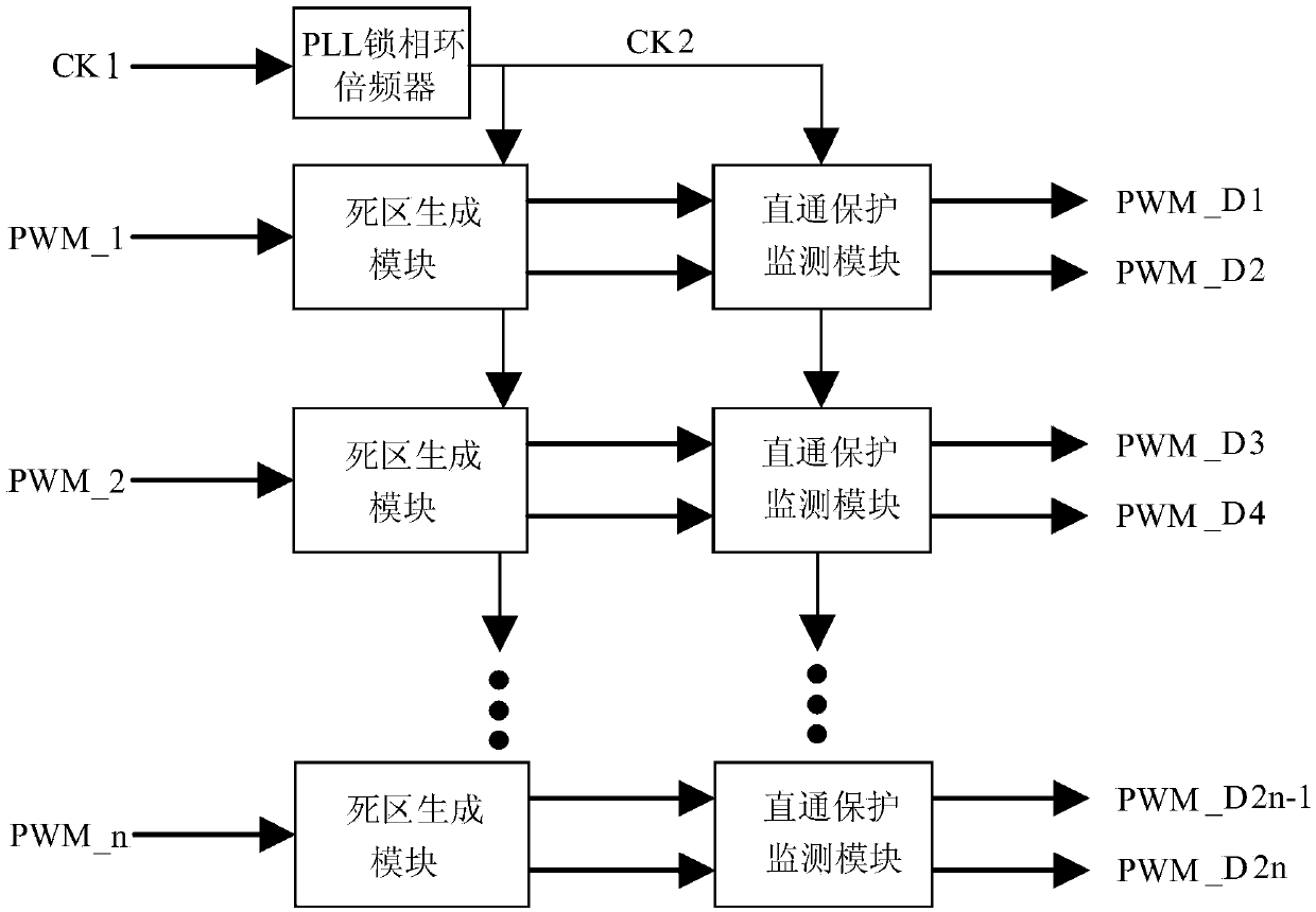
[0037] see Figure 1 ~ Figure 2 . It should be noted that the diagrams provided in this embodiment are only schematically illustrating the basic idea of ​​the present invention, and only the components related to the present invention are shown in the diagrams rather than the number, shape and shape of the components in actual implementation. Dimensional drawing, the type, quantity and proportion of each component can be changed arbi...


PUM


Abstract

The invention discloses a PWM wave dead zone generating circuit, and the PWM wave dead zone generating circuit comprises a frequency multiplier generating high frequency clock signal; a dead zone generating module generating PWM wave signal of band dead zone; a straight protection monitoring module monitoring and protecting the PWM wave signal of band dead zone generated by the dead zone generating module and avoiding short circuit while the switches are in breakover mode. The input clock signal is the low speed difference clock signal, the anti-interference performance is strong, the generated PWM wave signal and the PWM wave signal output by the main controller are kept on phase synchronization and the operation is easily realized; the PWM wave signal with dead zone is generated in a digital mode and the dead zone time is easily adjusted, the consistency is high; the PWM wave signal is generated by the frequency doubling high speed clock for greatly raising the precision; the PWM wave signal and the clock signal are transmitted, the transmission cable for multi-path transmission is little and simple and the interference is small.

Description

technical field [0001] The invention relates to the field of power electronic control, in particular to a PWM wave dead zone generation circuit. Background technique [0002] Power electronics technology is one of the most widely used technologies in the 21st century. With the increasing role of power electronics technology in the national economy, the development of power electronics technology is also very rapid. Therefore, the requirements for the performance and reliability of power electronic systems are getting higher and higher. [0003] Typically in power electronic converters, PWM waves are used to control switching devices. The main controller generates control signals and PWM signals; the drive circuit receives the control signals and PWM signals from the main controller, processes the control signals and PWM signals, and outputs PWM waves that meet the control requirements to control the switches in the power electronic converter device. Signal transmission mu...

Claims


Application Information

Patent Timeline
IPC IPC(8): H02M1/38H02M1/08
Inventor 张琨锋曹彬
Owner SHANGHAI ADVANCED RES INST CHINESE ACADEMY OF SCI
Features
  • Generate Ideas
  • Intellectual Property
  • Life Sciences
  • Materials
  • Tech Scout
  • Unparalleled Data Quality
  • Higher Quality Content
  • 60% Fewer Hallucinations
Learn More