
A high pressure filter device

A technology of high-pressure and high-pressure water pipes, applied in the direction of filtration and separation, separation methods, chemical instruments and methods, etc., can solve the problems of mold frame deformation and leakage, high cost, deformation of tie rods, etc., and achieve low moisture content, long life and wide application range Effect

Active Publication Date: 2016-03-09
广东翔俊环保设备有限公司
View PDF9 Cites 5 Cited by
  • Summary
  • Abstract
  • Description
  • Claims
  • Application Information

AI Technical Summary

Problems solved by technology

[0002]The traditional membrane filter press inputs a certain pressure of water flow and air flow to make the membrane bulge and press the filter cake, thereby achieving further dehydration of the filter cake, but limited by the pressure The mechanical strength and sealing performance of the filter. The traditional diaphragm filter press can only reach a working pressure of 2MPa. No matter how high the pressure is, it is easy to cause deformation of the tie rod or deformation of the mold frame. Under such a pressure value, the dehydrated The water content in the filter cake is still very high, and the dehydrated filter plate needs to be dried and other processes before it can be directly used as other raw materials, which is extremely inconvenient and expensive for subsequent transportation and processing.

Method used


Image

  • A high pressure filter device
  • A high pressure filter device
  • A high pressure filter device

Examples


Embodiment Construction

[0025] The purpose of the invention of the present invention will be described in further detail below in conjunction with the accompanying drawings and specific embodiments, and the embodiments will not be described one by one if it is clear enough, and the implementation of the present invention is not therefore limited to the following embodiments.

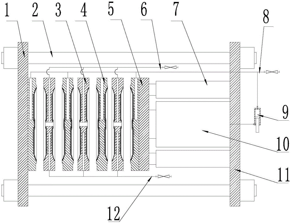
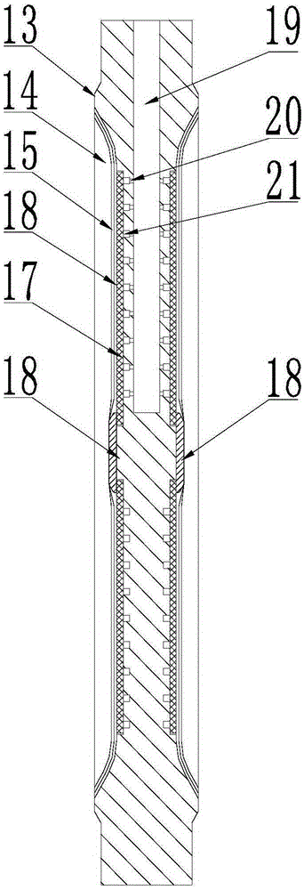
[0026] Such as Figure 1 to Figure 5 As shown, the high-pressure filter press device includes a main frame and a material mold 3 installed in the main frame, a water mold 4 and a movable beam 5, and the main frame includes a left beam 1, a right beam 11 and fixedly connected to the The tie rods 2 between the left beam 1 and the right beam 11, between the left beam 1 and the movable beam 5 are alternately arranged in parallel with the material mold 3 and the water mold 4 that form a closed filter chamber 35 when the mold is closed, The upper part of the water mold 4 is provided with a water inlet channel 19, at least one of the ...


PUM


Abstract

The invention discloses a high-pressure filter pressing device which comprises a main frame, material molds, water molds and a movable beam plate, wherein the material molds, the water molds and the movable beam plate are mounted in the main frame; the main frame comprises a left beam plate, a right beam plate and pull rods which are fixedly connected between the left beam plate and the right beam plate; the high-pressure filter pressing device also comprises a hydraulic cylinder; by using the movable beam plate, a part between each water mold and the corresponding material mold can be opened or closed under the action of the hydraulic cylinder; when the molds are closed, a closed filter chamber is formed between the water mold and the material mold which are adjacent; the hydraulic cylinder comprises a main cylinder and blank pressing cylinders; a piston rod of each blank pressing cylinder acts on the edge of the movable beam plate; a piston rod of the main cylinder acts on the middle of the movable beam plate; a pressure conversion cylinder is connected between the main cylinder and a high-pressure water path through a pipeline. According to the high-pressure filter pressing device disclosed by the invention, by arranging the pressure conversion cylinder, in the high-pressure extrusion dehydrating process, the water content of a filter cake is greatly reduced and the problem that a mold frame is damaged by crushing or leaks materials can be avoided through dynamic pushing force balance. The high-pressure filter pressing device has the advantages of simple structure, high safety and reliability, long service life and wide application range.

Description

technical field [0001] The invention relates to the field of slurry dehydration, in particular to a high-pressure filter press device. Background technique [0002] The traditional diaphragm filter press inputs a certain pressure of water flow and air flow to make the diaphragm bulge and press the filter cake, thereby achieving further dehydration of the filter cake, but limited by the mechanical strength and sealing of the filter press, the traditional diaphragm filter press only The working pressure can reach 2MPa. No matter how high the pressure is, the deformation of the tie rod or the leakage of the mold frame will easily occur. However, under such a pressure value, the moisture content in the dehydrated filter cake is still high, and the dehydrated filter plate is still high. It needs to be processed by other processes such as drying before it can be directly used as other raw materials, which is extremely inconvenient and expensive for subsequent transportation and pr...

Claims


Application Information

Patent Timeline
IPC IPC(8): B01D25/12
Inventor 王骏
Owner 广东翔俊环保设备有限公司
Learn More