Metal plastic swaging forming method

Active Publication Date: 2014-12-24
ZHUZHOU WENJIA IND
View PDF6 Cites 3 Cited by
  • Summary
  • Abstract
  • Description
  • Claims
  • Application Information

AI Technical Summary

Problems solved by technology

[0004] The connection between the existing extrusion forging head and the piston rod of the main cylinder is generally threaded connection. Within the range of thread strength, the extrusion forging head directly acts on the surface of the workpiece blank with hydraulic energy, thereby deforming the workpiece blank
The extrusion forging head is in contact with the workpiece blank for one-time extrusion forging. Due to the large force-bearing area, a large pressure must be required to cause the workpiece blank to undergo plastic deformation. Extrusion forging is difficult and requires a large extrusion forging force. The performance of the system and the mold puts forward higher requirements, and the equipment cost and energy consumption are also greatly increased; and if multiple deformations are used, multiple extrusion forgings of multiple equipment are required to meet the precision requirements of parts, etc. As a result, the existing forming equipment and energy supply system are complicated, the equipment is bulky, large in investment, and high in cost; in addition, because the workpiece blank reaches the required shape through one-time continuous plastic deformation, the internal crystal phase structure of the metal flows during the extrusion forging process. High resistance, which will also affect the internal structural performance of the molded workpiece and reduce the quality of the molded workpiece
[0005] In addition, the current metal extrusion forging equipment adopts the open extrusion forging method, that is, the cavity of the mold is formed by the cooperation of the extrusion forging head and the open mold cavity, and the workpiece blank is squeezed between the extrusion forging head and the mold cavity before it is fully formed. In the process of extrusion and forging, the workpiece blank is prone to bending deformation, resulting in the inability to fully enter the mold cavity, resulting in defective products, which will also reduce the service life of the mold, and even damage the mold
Moreover, the current metal extrusion forging equipment cannot extrude and form through holes on the workpiece blank at one time. When the workpiece with holes is to be obtained, it needs to be reprocessed after extrusion forging, which has the disadvantages of complex procedures, low production efficiency, and high cost.

Method used


Image

  • Metal plastic swaging forming method
  • Metal plastic swaging forming method
  • Metal plastic swaging forming method

Examples


Embodiment 1

[0028] A metal plastic extrusion forging method, comprising the following steps:

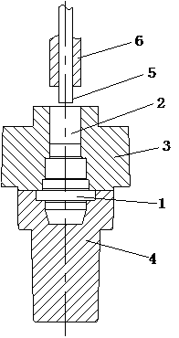
[0029] (1) Prepare extrusion forging equipment (such as figure 1 shown), the extrusion forging equipment has an openable and closed cavity 1 and a first extrusion channel 2 communicating with the cavity 1; the openable and closed cavity 1 is formed by the upper The mold 3 and the lower mold 4 are formed, and the first extrusion forging channel 2 is arranged on the upper mold 3;

[0030] (2) Steps of feeding and extrusion, to open the cavity 1, put the workpiece blank into the cavity 1 or the first extrusion forging channel 2, and close the cavity 1 after closing the mold, and adopt the extrusion end face size smaller than the first extrusion forging The first punching part 5 of the cross-sectional size of the channel 2 is inserted into the first extrusion forging channel 2 to squeeze holes on the workpiece blank, and the workpiece blank produces a plastic deformation;

[0031] (3) In the formi...

Embodiment 2

[0039] A metal plastic extrusion forging method, comprising the following steps:

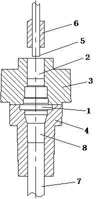
[0040] (1) Prepare extrusion forging equipment (such as figure 2 shown), the extrusion forging equipment has an openable and closed cavity 1 and a first extrusion channel 2 communicating with the cavity 1; the openable and closed cavity 1 is formed by the upper The mold 3 and the lower mold 4 are formed, and the first extrusion forging channel 2 is arranged on the upper mold 3 . The extruding and forging molding equipment also has a second extruding hole member 7 and a second extruding forging channel 8 communicated with the cavity 1, the second extruding forging channel 8 is arranged in the lower die 4, and the cross-sectional size of the second extruding hole member 7 is the same as that of the first forging channel. The cross-sectional dimensions of the two extrusion forging channels 8 are consistent, and the second extrusion forging channel 8 is coaxial and opposite to the first extrusion ...

Embodiment 3

[0049] A metal plastic extrusion forging method, comprising the following steps:

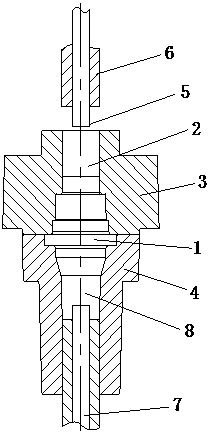
[0050] (1) Prepare extrusion forging equipment (such as image 3 shown), the extrusion forging equipment has an openable and closed cavity 1 and a first extrusion channel 2 communicating with the cavity 1; the openable and closed cavity 1 is formed by the upper The mold 3 and the lower mold 4 are formed, and the first extrusion forging channel 2 is arranged on the upper mold 3 . The extruding and forging molding equipment also has a second extruding hole member 7 and a second extruding forging channel 8 communicated with the cavity 1, the second extruding forging channel 8 is arranged in the lower die 4, and the cross-sectional size of the second extruding hole member 7 is the same as that of the first forging channel. The cross-sectional dimensions of the two extrusion forging channels 8 are consistent, and the second extrusion forging channel 8 is coaxial and opposite to the first extrusion f...


PUM


Abstract

The invention discloses a metal plastic swaging forming method. The metal plastic swaging forming method comprises the steps of swaging forming equipment preparation, feeding and hole extrusion, forming and discharging. By adopting hoe extrusion, avoidance and swaging in a closed cavity, a workpiece blank is plastically deformed in two steps to obtain a formed workpiece. The metal plastic swaging forming method has the advantages that the needed swaging force is small, the forming is easy, the energy consumption is low, the working efficiency is high, the requirements on equipment parts and a power system are low, the swaging forming difficulty can be reduced, the internal property and quality of the formed workpiece are improved and the like.

Description

technical field [0001] The invention relates to the technical field of metal extrusion forging, in particular to a metal plastic extrusion forging method. Background technique [0002] Metal extrusion and forging technology is a method of pressure processing using the principle of metal plastic forming. Put the pretreated metal workpiece blank into the mold, and then apply pressure on the metal workpiece blank to deform the metal workpiece blank and fill the mold shape. cavity to obtain the required parts. Metal extrusion and forging technology is an advanced technology with less cutting or no cutting, which is conducive to improving the quality of products, improving the internal microstructure and performance of products, and also has the advantages of material saving, low energy consumption, wide application range and flexible production It has the characteristics of high reliability, simple process flow and low investment in equipment. [0003] At present, there are st...

Claims


Application Information

Patent Timeline
Patent Type & Authority Applications(China)
IPC IPC(8): B21J5/02
Inventor 龙西新
Owner ZHUZHOU WENJIA IND
Why Eureka
Try Eureka