
Concentrated and integrated sand and water separation device
A sand-water separation and concentrator technology, applied in chemical instruments and methods, water/sewage multi-stage treatment, water/sludge/sewage treatment, etc., can solve problems such as zero contribution, to promote retention, strengthen removal, and promote The effect of carbon source release
- Summary
- Abstract
- Description
- Claims
- Application Information
AI Technical Summary
Problems solved by technology
Method used
Image

Examples
Embodiment
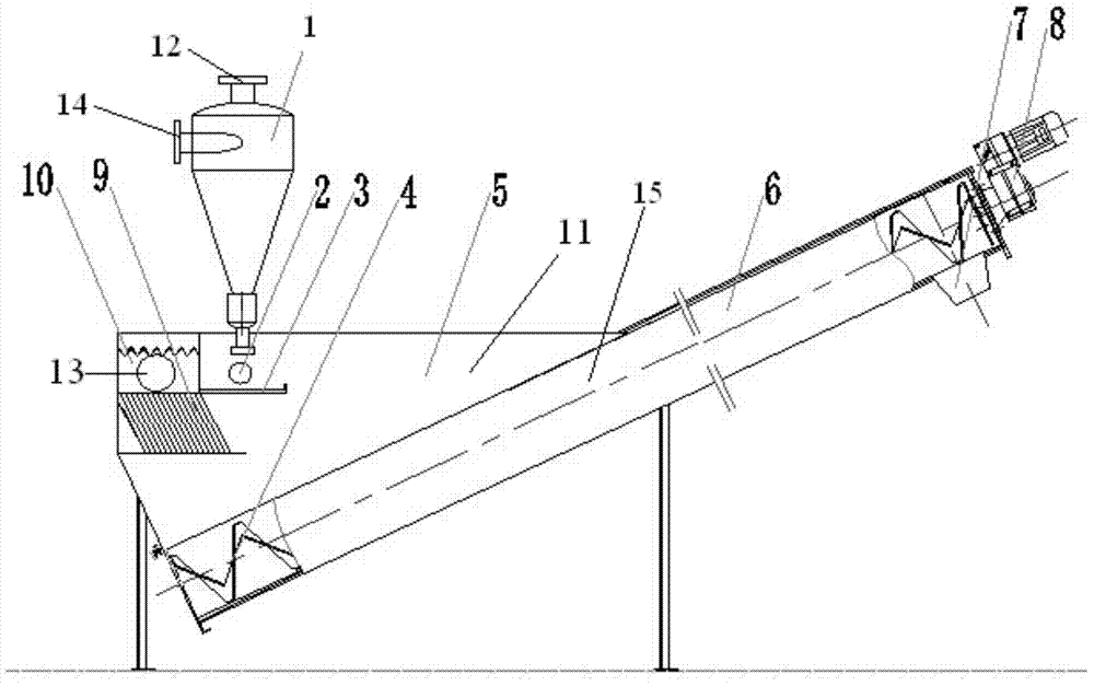
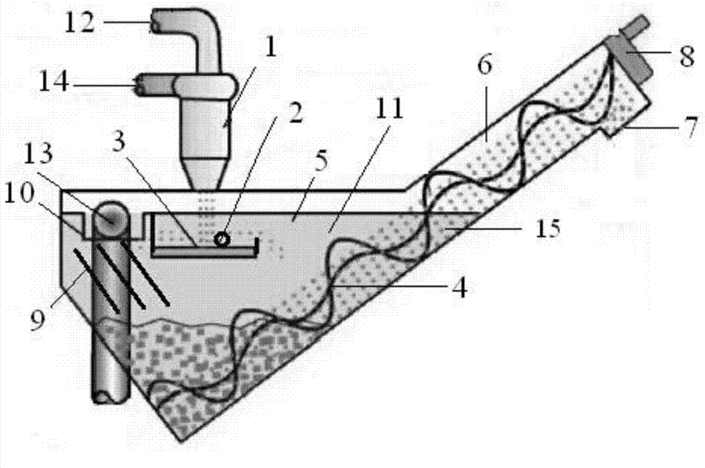
[0020] Such as figure 1 As shown, the present invention mainly includes a sand material concentrator 1 and a sand water separator 11; the sand material concentrator 1 is provided with a sand water mixture inlet 14 and an overflow pipe outlet 12; the sand water separator 11 includes a collecting hopper water tank 5 and a spiral sand washer 15. The spiral sand washer 15 includes a stirring fluidization screw 4, a delivery tank 6 and a driving device 8. The stirring fluidization screw 4 is located in the delivery tank 6 and is driven by the driving device 8 drive, one end of the delivery tank 4 is provided with a sand discharge port 7, and the other end obliquely extends downward to the bottom of the collecting hopper water tank 5, the used stirring and fluidizing screw is a shaftless screw, and the delivery tank is a U-shaped groove; The upper part of the side wall of the hopper water tank 5 is provided with a jet water inlet 2, and the interior of the hopper water tank is provi...
PUM
| Property | Measurement | Unit |
|---|---|---|
| particle diameter | aaaaa | aaaaa |
Abstract
Description
Claims
Application Information