Engine exhaust pipe heat shield

A technology for engines and exhaust pipes, which is applied in the direction of engine components, machines/engines, exhaust devices, etc., can solve problems such as the inability to effectively block high-temperature heat radiation of exhaust pipes, and achieve improved working environment temperature and good heat insulation effect , the effect of preventing catastrophic events

Inactive Publication Date: 2014-12-24
广西玉林盈龙橡塑科技有限公司
View PDF4 Cites 2 Cited by
  • Summary
  • Abstract
  • Description
  • Claims
  • Application Information

AI Technical Summary

Problems solved by technology

When the existing diesel engine is working normally, the surface temperature of the exhaust pipe is generally 300°C-600°C. The exhaust pipe heat shield used is a heat shield made of single metal material. When the surface temperature of the exhaust pipe rises due to external radiation , the surface temperature of the single-layer metal heat shield rises synchronously with the surface temperature of the exhaust pipe, so it cannot effectively block the high-temperature heat radiation from the exhaust pipe when the engine is working
Especially when the fuel pipe of the engine bursts after being impacted, the fuel is directly sprayed to the exhaust pipe and the surface of the heat shield, causing a catastrophic accident of engine combustion

Method used


Image

  • Engine exhaust pipe heat shield
  • Engine exhaust pipe heat shield
  • Engine exhaust pipe heat shield

Examples


Embodiment 1

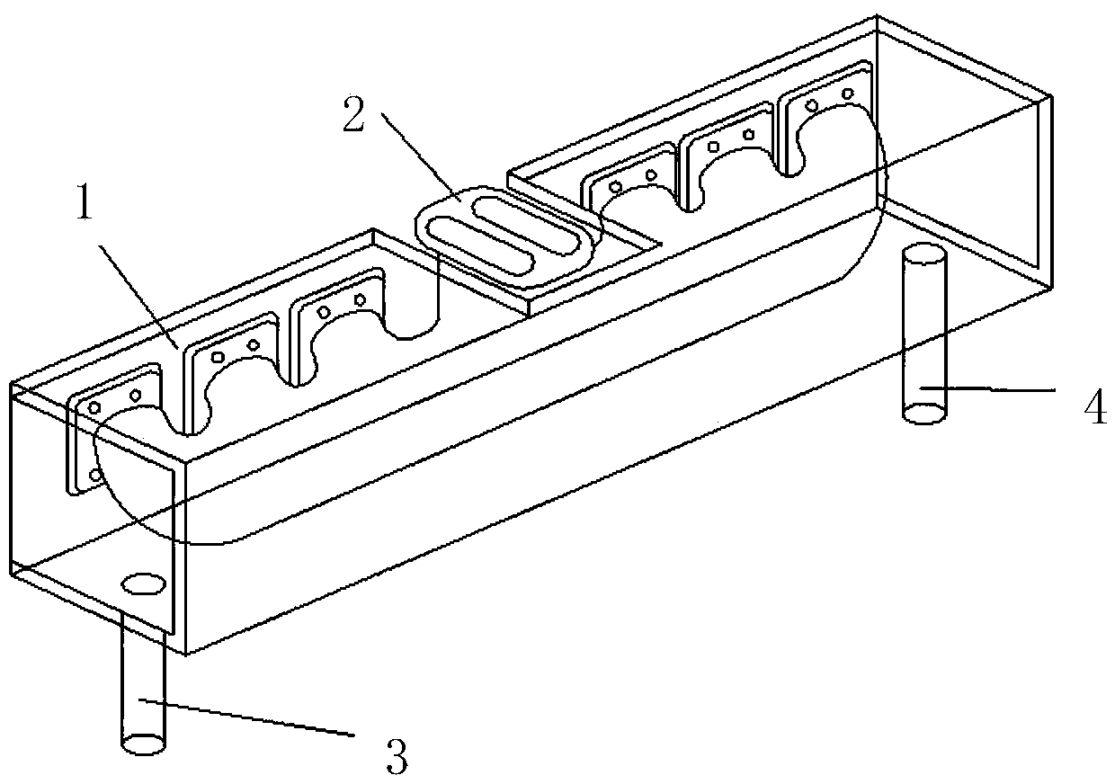
[0013] Embodiment one: if figure 1 As shown, the engine exhaust pipe heat shield is made of a hollow interlayer sleeve 1 that fully seals the engine exhaust pipe 2, and the hollow interlayer sleeve 1 has a cooling water inlet 3 and a cooling water outlet 4 connected to the engine cooling water cycle. The heat of the hollow interlayer sleeve 1 can be continuously taken away by the engine cooling water circulation, and its surface temperature can be kept below 70 degrees to achieve the purpose of isolating the high-temperature heat source of the engine exhaust pipe, preventing fuel fire accidents and reducing the temperature of the engine compartment. Simple and effective heat shield for engine exhaust pipe insulation.

Embodiment 2

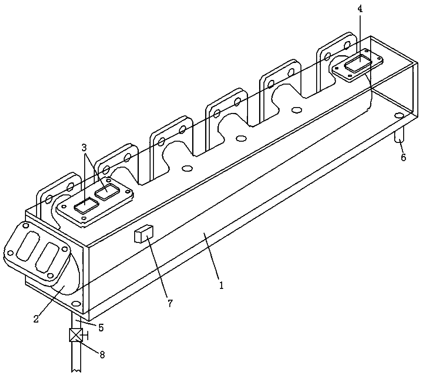
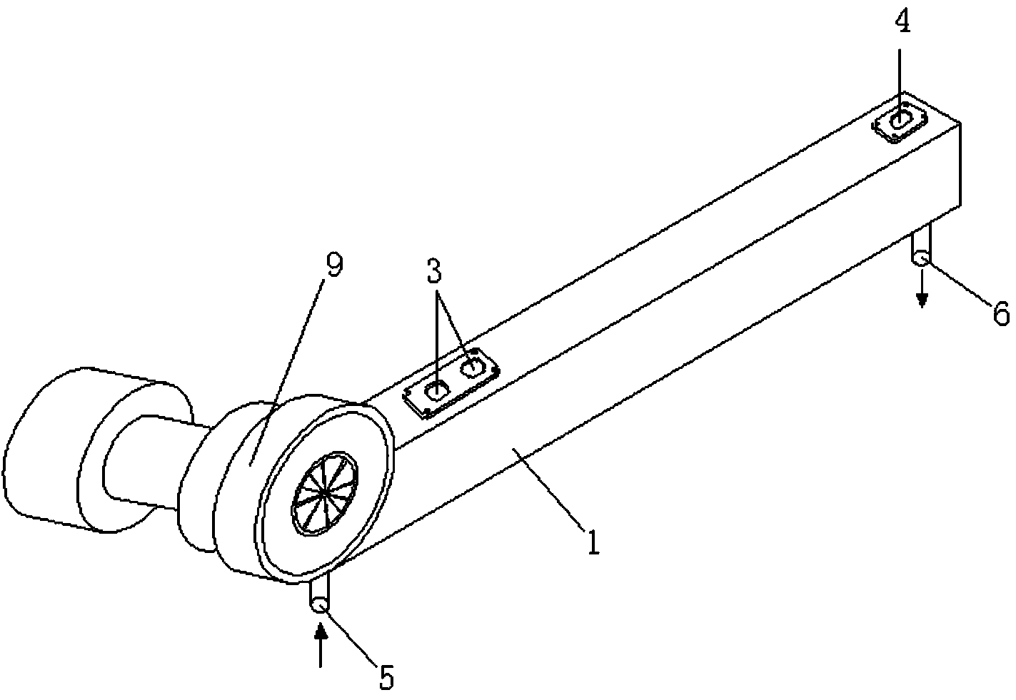
[0014] Embodiment two: if figure 2 , image 3 , Figure 4 As shown; the engine exhaust pipe heat shield is composed of a hollow interlayer sleeve 1 fully sealed engine exhaust pipe 2 and a turbocharger connecting pipe 9, and there are 2 groups of cooling water inlets and cooling water outlets on the hollow interlayer sleeve 1 , the cooling water inlet 3 and the cooling water outlet 4 are connected to the circulating cooling water of the engine, and the cooling water inlet 5 and the cooling water outlet 6 are connected to supplementary cooling water through the solenoid valve 8. When the water circulation is not enough to reduce the temperature of the hollow interlayer jacket 1, start supplementary cooling water, such as figure 2 , image 3 , Figure 4 As shown, a temperature sensor 7 is provided on the hollow interlayer sleeve 1, and the electromagnetic water valve 8 in the supplementary cooling water pipeline is controlled by a control circuit. The setting of the tempe...


PUM


Abstract

The invention relates to the field of engine parts, in particular to an engine exhaust pipe heat shield. The engine exhaust pipe heat shield is characterized in that a hollow sandwiched jacket 1 which is fully sealed is arranged outside an engine exhaust pipe 2, one or two sets of cooling water inlets and cooling water outlets are arranged in the hollow sandwiched jacket 1, one group of cooling water inlets 3 and cooling water outlets 4 are connected with engine circulating cooling water, the other group of cooling water inlets 3 and cooling water outlets 4 are connected with supplementary cooling water. A temperature sensor 7 is arranged on the hollow sandwiched jacket 1. A control circuit controls an electromagnetic water valve 8 arranged in a supplementary cooling water pipeline. The hollow sandwiched jacket 1 covers the engine exhaust pipe 2 and a turbocharger connecting pipe 9. The engine exhaust pipe heat shield is in the hollow sandwiched water-cooled structure, burning accident of the engine can be effectively prevented, ambient temperature of the engine can be decreased even at normal times, operating efficiency of the engine is improved, and the service life of the engine is prolonged.

Description

technical field [0001] The invention relates to the field of engine components, in particular to an engine exhaust pipe heat shield. Background technique [0002] When the engine is running normally, the high-temperature exhaust gas after the combustion of gas in the cylinder is discharged through the exhaust pipe. Since these high-temperature exhaust gases carry a large amount of heat, the temperature of the exhaust pipe is high when the engine is exhausted through the exhaust pipe. And to dissipate heat around it, which leads to an increase in the temperature in the engine compartment. In order to reduce the heat radiation of the engine to other parts, prolong the service life, and ensure the normal operation and safety of the engine, people use a heat shield to isolate the exhaust pipe. Open, heat-insulate the exhaust pipe of high-temperature gas. When the existing diesel engine is working normally, the surface temperature of the exhaust pipe is generally 300°C-600°C. Th...

Claims


Application Information

Patent Timeline
Patent Type & Authority Applications(China)
IPC IPC(8): F01N13/14F01N13/08
Inventor 赵阿祥朱征东
Owner 广西玉林盈龙橡塑科技有限公司
Why Eureka
Try Eureka