
Testing method for simulating launching impact overload in chamber

A test method and technology of simulating chambers, applied in the field of testing, can solve problems such as complex process, many uncontrollable factors, and difficulty in grasping performance evolution behavior, so as to achieve the effect of simple method and avoiding complicated operation

Active Publication Date: 2014-12-24
NO 53 RES INST OF CHINA NORTH IND GRP
View PDF4 Cites 4 Cited by
  • Summary
  • Abstract
  • Description
  • Claims
  • Application Information

AI Technical Summary

Problems solved by technology

The live ammunition shooting test is not only complicated in process, with many uncontrollable factors and high cost, but also it is difficult to measure the dynamic mechanical response parameters of the projectile and arrow components during the firing process, and it is difficult to grasp its performance evolution behavior in high impact overload, which cannot provide information for the design work. effective data support
Moreover, in the process of research and development of new materials and new products, insufficient basic data can easily lead to test accidents. If the live ammunition shooting test fails, it may cause fatal damage to the launching weapon and cause irreparable huge losses
[0003] At present, there is no report on the evaluation technology of overload launch conditions in the bore of simulated barrel weapons

Method used


Image

  • Testing method for simulating launching impact overload in chamber
  • Testing method for simulating launching impact overload in chamber
  • Testing method for simulating launching impact overload in chamber

Examples


Embodiment 1

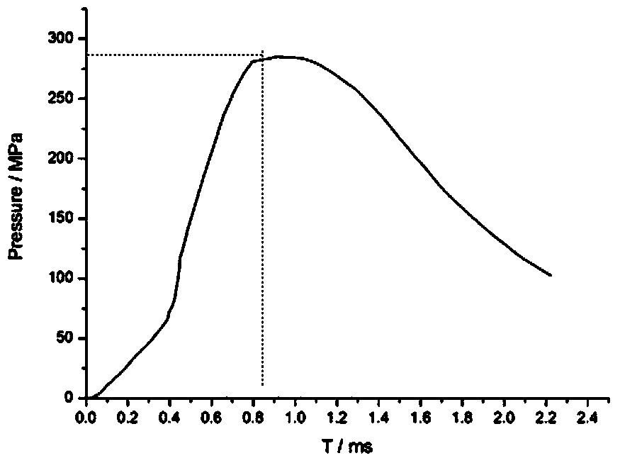
[0031] Taking the simulation of the firing process of a gun as an example, the p-t curve of the chamber pressure when the gun is launched is as figure 2 As shown, the loading time for the chamber pressure to reach the peak is 0.85ms, and the maximum chamber pressure is 285MPa.

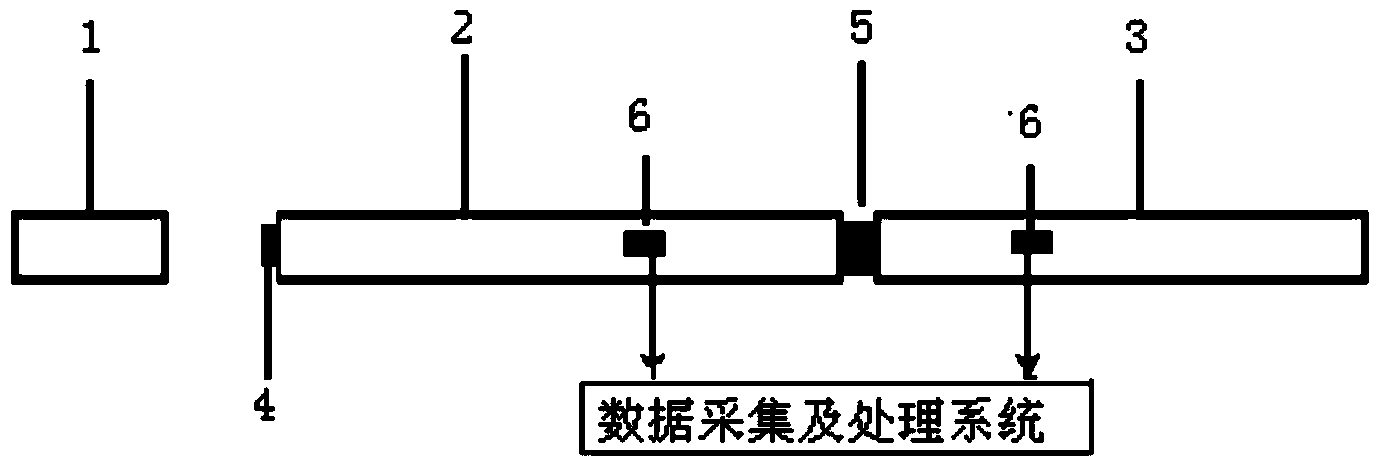
[0032] The striking rod 1, the loading rod 2 and the transmission rod 3 are all cylindrical rods with a diameter of 80mm, the material is 40CrNiMoA, the yield strength is 835MPa, and the density is 7.85×10 3 kg / m 3 , The longitudinal wave velocity is 5000m / s. The length of the striking rod 1 is 2000 mm, the length of the loading rod 2 is 4000 mm, and the length of the transmission rod 3 is 4000 mm. The shaper 4 is a brass sheet of Φ30mm×3mm. By type It is calculated that the predetermined strike speed of the stick 1 is 14.5m / s. The tested sample 5 is a cylindrical resin-based carbon fiber reinforced composite material with an outer diameter of 74mm, an inner diameter of 60mm, and a length of 75mm.

[00...

Embodiment 2

[0037] In the loading process of the bore pressure simulated in this embodiment, the maximum bore pressure is 300 MPa, and the loading time before the bore pressure reaches the peak value is 0.45 ms.

[0038] The striking rod 1, the loading rod 2 and the transmission rod 3 are all cylindrical rods with a diameter of 100mm, the material is 37CrNi3, and the yield strength is 980MPa. The length of the striking rod 1 is 1200 mm, the length of the loading rod 2 is 3500 mm, and the length of the transmission rod 3 is 3500 mm. The shaper 4 is a brass sheet of Φ40mm×4mm. By type It is calculated that the predetermined strike speed of the stick 1 is 15.3 m / s. The tested sample 5 is the same as the first embodiment.

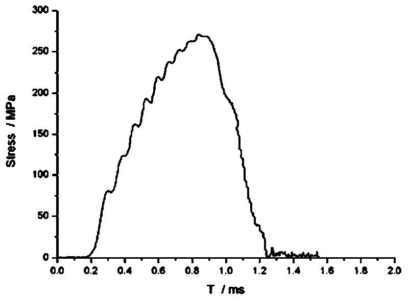
[0039] The striking rod 1 is driven by 2.4Mpa high-pressure gas, and the measured striking speed is 15.6m / s. The loading stress wave waveform measured by the test is as Figure 5 As shown, the maximum loading intensity of the loading stress wave is 302 MPa, and the loading ...

Embodiment 3

[0041] In the loading process of the bore pressure simulated in this embodiment, the maximum bore pressure is 500 MPa, and the loading time before the bore pressure reaches the peak is about 0.3 ms.

[0042] The striking rod 1, the loading rod 2 and the transmission rod 3 are all cylindrical rods with a diameter of 110mm, the material is 35CrMnSiA, and the yield strength is 1280MPa. The length of the striking rod 1 is 800 mm, the length of the loading rod 2 is 3200 mm, and the length of the transmission rod 3 is 3200 mm. The shaper 4 is a brass sheet of Φ60mm×6mm. By type It is calculated that the predetermined strike speed of the stick 1 is 25.5m / s. The tested sample 5 is a cylindrical resin-based carbon fiber reinforced composite material with an outer diameter of 70 mm, an inner diameter of 20 mm, and a length of 50 mm.

[0043] The driving source is ballistic gunpowder gas, which is launched with a 120mm smoothbore barrel. There are two nylon elastic bands on the striking r...


PUM

PropertyMeasurementUnit
Yield strengthaaaaaaaaaa
Diameteraaaaaaaaaa
Yield strengthaaaaaaaaaa

Abstract

The invention belongs to the technical field of testing. A chamber pressure p-t curve during live launch is simulated by using stress generated during rod-rod collision, and loading stress wave control is realized through the parameters of a testing rod, a reshaper and the like. In a testing method for simulating launching impact overload in a chamber related to the invention, a Hopkinson pressure lever dynamic compression testing method is adopted, and the steps of testing condition setting, testing preparation, testing and data processing are carried out; the length L of a striking rod is (0.45-0.55)ct; the lengths of a loading rod 2 and a transmission rod 3 are not smaller than two times of the length L of the striking rod 1; the striking speed is calculated according to a formula in the specifications; the reshaper 4 is a circular brass strip. By adopting an experimental method related to the invention, different chamber pressure curves can be simulated; meanwhile, the dynamic mechanical property of a test sample under a simulation chamber pressure loading condition can be obtained. The method is easy to operate, and is effective, safe and controllable. The method is suitable for simulating performance verification and evaluation of members in the chambers of barrel weapons, and data support is provided for the design and manufacturing of missile and weapon members.

Description

Technical field [0001] The invention belongs to the field of testing technology, relates to dynamic testing technology, and particularly relates to simulation testing technology of ammunition launching impact overload. Background technique [0002] The firing of barrel weapons is an extremely complex dynamic process. In-bore projectile weapon components (such as projectiles, stocks, engine shells, etc.) have to withstand the instantaneous high-pressure impact from the deflagration of gunpowder, and generally projectiles are fired in the chamber. The process is extremely short (tens of microseconds to ten milliseconds), and the pressure in the chamber is as high as 250-700MPa. During the launch process, under such a high impact load, the reliability of component performance is very important to the stability and accuracy of projectile launching. Therefore, it is necessary to assess and evaluate the performance of components under high launch overload conditions. At present, the p...

Claims


Application Information

Patent Timeline
IPC IPC(8): F41A31/00
Inventor 彭刚冯家臣王绪财陈刚王伟刘原栋陈春晓
Owner NO 53 RES INST OF CHINA NORTH IND GRP
Learn More