Stranding machine for producing power supply cable of hydraulic pump station

A technology for power supply cables and hydraulic pump stations, applied in the field of stranding machines, can solve the problems of easy deformation, relaxation, and the separation of the pay-off frame from the equipment, so as to avoid damage, balance the operation of the stranding machine, and avoid loose strands and twists. Effect

Inactive Publication Date: 2014-12-24
SICHUAN DINGRUI HYDRAULIC EQUIP MFR
View PDF5 Cites 3 Cited by
  • Summary
  • Abstract
  • Description
  • Claims
  • Application Information

AI Technical Summary

Problems solved by technology

However, in the support structure, those connected parts and devices not only have to perform back-twisting activities, but also bear the huge force brought by the rotation of the equipment. There is a very large friction force between them, and the four fastening bolts at the right end of the flange shaft are disturbed by the strain force, and they are loose or even disconnected, so that the pay-off frame is separated from the equipment

Method used


Image

  • Stranding machine for producing power supply cable of hydraulic pump station
  • Stranding machine for producing power supply cable of hydraulic pump station
  • Stranding machine for producing power supply cable of hydraulic pump station

Examples


Embodiment 1

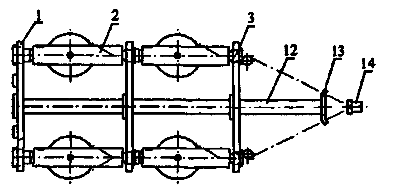
[0021] A stranding machine for producing power supply cables for hydraulic pump stations, used for the stranding cage in the cage stranding machine, which includes a first winch 1, a pay-off frame 2, a second winch 3, a main shaft 12, and a distribution board 13 and the paralleling die 14, the first capstan 1, the second capstan 3, the splitter plate 13 and the paralleling die 14 are sequentially set on the main shaft 12 from left to right.

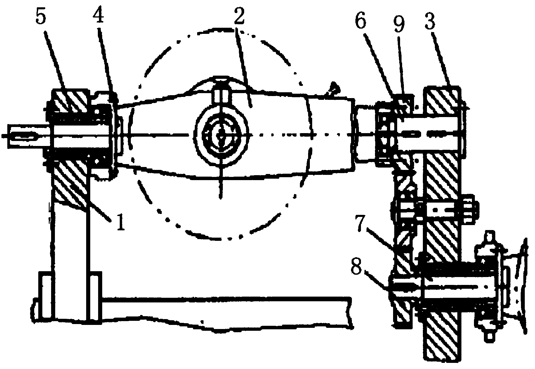
[0022] Two groups of pay-off frames 2 are placed between the first capstan 1 and the second capstan 3 one above the other, and a wire reel and a tension device are placed on each group of pay-off frames 2 . Both ends of each set of pay-off frame 2 are bored with through holes, the left end of the pay-off frame 2 is connected with the first half shaft 4, the first half shaft 4 is fixedly connected with the first centering shaft 5 through the bushing, and the first centering shaft 5 is set on the first half shaft 4 and fixedly connected wit...

Embodiment 2

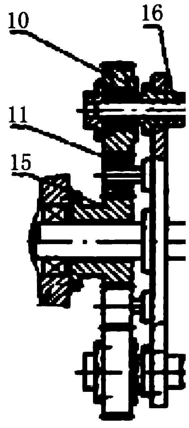
[0025] On the basis of Embodiment 1, the sleeve between the first half shaft 4 and the first centering shaft 5 is an unloading sleeve 16, and the first centering shaft 5 is sleeved in the unloading sleeve 16 in the form of a spline shaft , the first centering shaft 5 with the unloading sleeve 16 is set in the through hole of the first winch 1 as a whole, and the unloading sleeve 16 is connected with the through hole of the first winch 1; There is a spline cover, the spline cover at the right end of the first centering shaft 5 is fixedly connected in the through hole at the left end of the pay-off frame by means of screw connection, the spline cover at the left end of the first centering shaft 5 is connected to the twist-back gear 10 Fixed connection. Therefore, the gear drives the pay-off frame to rotate through the spline cover and the spline shaft.

[0026] An unloading sleeve is also arranged between the first centering shaft and the first capstan. The huge inertial centri...

Embodiment 3

[0028] The second centering shaft 6 is a flange shaft, and the end face of the second centering shaft 6 is fastened on the second capstan 3 with 6 M12 screws. The second centering shaft 6 is equipped with a self-aligning bearing, and the right end of the pay-off frame 2 is The through hole is set on the self-aligning bearing.


PUM


Abstract

The invention discloses a stranding machine for producing a power supply cable of a hydraulic pump station and relates to a pay-off rack supporting mechanism of a cage type stranding machine. The stranding machine comprises a stranding cage, the stranding cage comprises a first winch, pay-off racks, a second winch, a spindle, a wire distributor plate and a wire doubling mold, wherein the spindle is sleeved with the first winch, the second winch, the wire distributor plate and the wire doubling mold in sequence at intervals, the two sets of pay-off racks are placed between the first winch and the second winch with one set of pay-off rack above the other set of pay-off rack, a wire coil and a tension device are placed on each set of pay-off rack, the left end of each set of pay-off rack is connected with a first half shaft which is connected with a first spigot shaft through a shaft sleeve, each first half shaft is sleeved with the corresponding first spigot shaft, the first spigot shafts are fixedly connected with the first winch, a back-twist mechanism is connected to the tail end of each first spigot shaft, the right end of each set of rack-off rack is connected with a second spigot shaft which is arranged in a through hole in the right end of the pay-off rack in a sleeved mode and fixedly connected with the second winch, back-twist gear sets are connected to the second winch through second half shafts, the second spigot shafts are sleeved with gears, and the gears are meshed with the back-twist gear sets.

Description

technical field [0001] The invention relates to a wire stranding machine, in particular to a cage type wire stranding machine, in particular to a wire stranding machine used for producing power supply cables of a hydraulic system. Background technique [0002] The cable is an indispensable connecting cable in electrical equipment. It is generally composed of the innermost conductive cable and multiple outer layers. The inner layer cable is twisted from multiple single wires. The production equipment used is a twisting machine. . [0003] Stranding machine is widely used in all kinds of soft / hard conductor wires (copper wire, enameled wire, tinned wire, copper-clad steel, copper-clad aluminum, etc.) , network wires, etc.) are twisted together with a single conductor to meet the technical requirements of the wire. According to the twisting method, the stranding machine can generally be divided into single stranding machine, pair stranding machine, high-speed stranding ma...

Claims


Application Information

Patent Timeline
Patent Type & Authority Applications(China)
IPC IPC(8): H01B13/02
Inventor 陈安民
Owner SICHUAN DINGRUI HYDRAULIC EQUIP MFR
Why Eureka
Try Eureka