Supercharge Your Innovation With Domain-Expert AI Agents!

Laser drive circuit and optical module

A technology for driving circuits and lasers, used in lasers, laser parts, semiconductor lasers, etc., can solve problems such as large laser output wavelength shift and large laser temperature difference

Active Publication Date: 2014-12-24
HISENSE BROADBAND MULTIMEDIA TECH
View PDF7 Cites 6 Cited by
  • Summary
  • Abstract
  • Description
  • Claims
  • Application Information

AI Technical Summary

Problems solved by technology

[0005] However, in the burst mode, when the laser in the ONU optical module is in the working state, the laser is in the heating state, and when the laser in the ONU optical module is in the non-working state, the laser is in the non-heating state, so the laser is working The temperature difference between the two different states of working and non-working is large; at the same time, because the output wavelength of the laser is closely related to the temperature, the temperature difference between the working and non-working states of the laser is large, resulting in the output wavelength of the laser. Big offset

Method used


Image

  • Laser drive circuit and optical module
  • Laser drive circuit and optical module
  • Laser drive circuit and optical module

Examples


Embodiment Construction

[0020] The following will clearly and completely describe the technical solutions in the embodiments of the present invention with reference to the accompanying drawings in the embodiments of the present invention. Obviously, the described embodiments are only some of the embodiments of the present invention, not all of them. Based on the embodiments of the present invention, all other embodiments obtained by persons of ordinary skill in the art without creative efforts fall within the protection scope of the present invention.

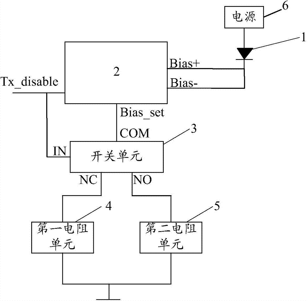
[0021] An embodiment of the present invention provides a laser drive circuit, such as figure 2 As shown, it includes: a laser 1 , a driver chip 2 , a switch unit 3 , a first resistance unit 4 , a second resistance unit 5 , and a power supply 6 .

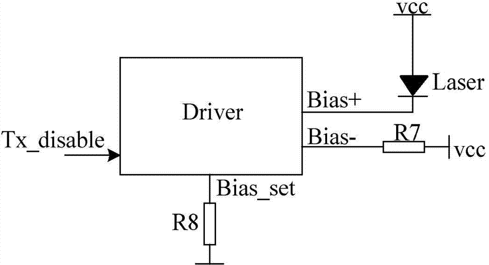
[0022] Before introducing the connection relationship of the above-mentioned components, the pins of the driving chip 2 will be described first. Such as figure 2 As shown, Bias+ and Bias- are the forward...


PUM


Abstract

An embodiment of the invention provides a laser drive circuit and an optical module, relates to the technical field of fiber optical communication and aims to reduce shift of output wavelength of a laser on the premise that an ONU (optical network unit) optical module is operated in a burst mode. The laser drive circuit is characterized in that when an input signal of a burst control signal pin of a driver chip is a first signal, bias current flowing through the laser passes through a common pin and a first pin of a switch unit to enable laser power outputted by the laser to be larger than or equal to a preset laser power; when an input signal of the burst control signal pin of the driver chip is a second signal, the bias current flowing through the laser passes through the common pin and a second pin of a switch unit to enable laser power outputted by the laser to be smaller than the preset laser power.

Description

technical field [0001] The invention relates to the technical field of optical fiber communication, in particular to a laser drive circuit and an optical module. Background technique [0002] With the progress of society and the rapid increase of information volume, people's demand for information transmission rate is also getting higher and higher. Therefore, a passive optical network (Passive Optical Network, PON for short) that can meet people's higher bandwidth and speed requirements emerges at the historic moment. [0003] In a PON system, it generally includes an optical line terminal (Optical Line Termination, referred to as OLT) optical module of the central office equipment and a plurality of optical network unit (Optical Network Unit, referred to as ONU) optical modules of the user side equipment; Multiple ONU optical modules communicate, therefore, multiple ONU optical modules need to communicate with the OLT optical module in a time-sharing manner. For example,...

Claims


Application Information

Patent Timeline
IPC IPC(8): H01S5/042H01S3/09
Inventor 薛登山赵其圣钟元文
Owner HISENSE BROADBAND MULTIMEDIA TECH
Features
  • R&D
  • Intellectual Property
  • Life Sciences
  • Materials
  • Tech Scout
  • Unparalleled Data Quality
  • Higher Quality Content
  • 60% Fewer Hallucinations
Learn More