
Quick charging system and method for power batteries of electric cars

A technology for electric vehicles and fast charging, which is applied in the direction of electric vehicles, secondary battery charging/discharging, battery circuit devices, etc., can solve the problems of battery polarization, reduce battery life, reduce charging efficiency, etc., and achieve excellent dynamic characteristics , Improve the charging speed and maintain the power

Active Publication Date: 2014-12-24
SHANDONG UNIV
View PDF7 Cites 12 Cited by
  • Summary
  • Abstract
  • Description
  • Claims
  • Application Information

AI Technical Summary

Problems solved by technology

In the early stage of charging, the battery can accept high current charging, but in the later stage of charging, the battery polarization phenomenon is serious, and the charging is slow. The three-stage charging method cannot solve the battery polarization phenomenon in the later stage of charging, and the pulse charging stops charging in the early stage, which wastes charging time.
2. In the topological structure of the depolarization circuit, resistors are generally connected in series at both ends of the battery, and the polarization of the battery is eliminated by using resistor discharge. Affected security
3. The judgment of the end of charging generally adopts comprehensive methods such as timing or current zero-increment. These methods only make the judgment of stopping charging after sampling the voltage, which has actually caused damage to the battery and reduced the battery life.
This invention uses positive and negative pulse charging to eliminate the polarization phenomenon in battery charging, but it does not notice that the battery polarization phenomenon is not serious at the initial stage of charging. At the same time, its negative pulse circuit adopts resistance discharge, which greatly wastes energy and reduces charging efficiency.

Method used


Image

  • Quick charging system and method for power batteries of electric cars
  • Quick charging system and method for power batteries of electric cars
  • Quick charging system and method for power batteries of electric cars

Examples


Embodiment Construction

[0032] The present invention is described in detail below in conjunction with accompanying drawing:

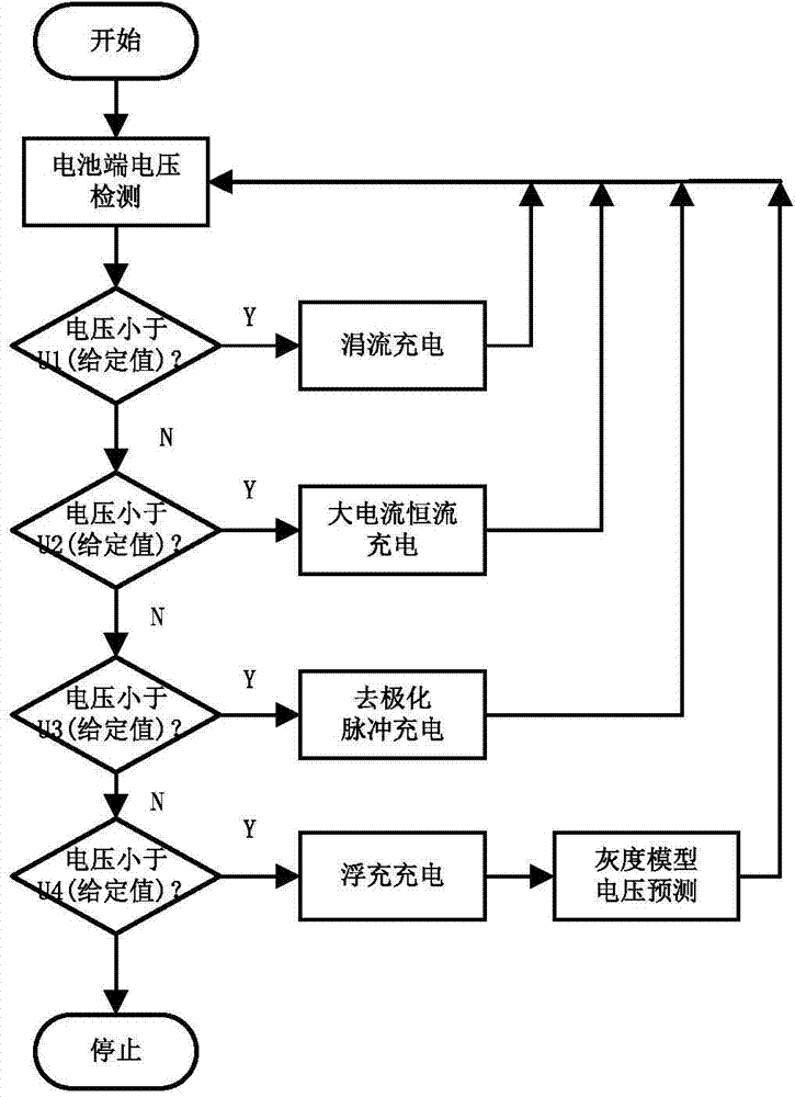
[0033] Such as figure 1 As shown, a fast charging system for electric vehicles includes a power frequency AC input power grid, a main circuit, a control circuit and an electric vehicle battery load; the input end of the main circuit is connected to the power frequency AC input power grid, and the output end of the main circuit is connected to the electric power grid Automotive load connection; the main circuit includes the sequence of electrical connections: fault protection module 1, input rectification and filtering module 2, half-bridge inverter module 3, high-frequency transformer 4, output rectification and filtering module 5, depolarization module 6, control circuit Including current and voltage sampling 7, DSP digital control module 8, IGBT drive module 9;

[0034] The DSP digital control module 8 is respectively connected to the input end of the fault protection modul...


PUM


Abstract

The invention discloses a quick charging system and method for power batteries of electric cars. The system comprises a fault protection module, the input end of the fault protection module is connected with the output ends of a power-frequency alternating-current input grid and a digital signal processor, the output end of the fault protection module is connected with an input rectifying and filtering module, a direct-current signal then passes through a half-bridge inverter circuit to transmit stored energy to a high-frequency transformer via opening of switch tubes, a full-wave rectifying circuit converts pulsed voltage outputted by the high-frequency transformer into direct-current voltage which is transmitted to an output direct-current filter circuit, the output direct-current filter circuit filters out smooth direct current flowing into an electric car battery load, and the electric car battery load is connected with the output end of the fault protection module through a depolarization module. By the system and method, quick charging to the power batteries is realized, battery polarization can be removed effectively, efficiency of a charger is improved by an energy recovery circuit, and service lives of the batteries are prolonged.

Description

technical field [0001] The invention relates to a fast charging technology for a power battery, in particular to a fast charging system and method for a power battery. Background technique [0002] With the advantages of energy saving, environmental protection and low emission, electric vehicles have become the most promising field in the modern automobile industry. The rapid development of electric vehicles has also brought higher requirements for electric vehicle power battery charging devices, specifically: fast charging, no damage to the battery, and safe and reliable charging. The shortcomings of the charging system in the electric vehicle charging market can be summarized into the following categories: 1. The charging method adopts a three-stage charging method of constant current and constant voltage or positive and negative pulse charging. In the early stage of charging, the battery can accept high current charging, but in the later stage of charging, the battery po...

Claims


Application Information

Patent Timeline
Patent Type & Authority Applications(China)
IPC IPC(8): H02J7/00H02J7/02H01M10/44H02J7/04
CPCY02E60/10
Inventor 崔纳新史永超张承慧孙波
Owner SHANDONG UNIV
Learn More