The composite girder having web members with various patterns

A composite beam and steel technology, applied in bridge materials, bridges, bridge construction, etc., can solve the problems of increased shear force, increased bending moment, increased weight, etc., and achieve the effect of improved resistance and reduced node scale

Inactive Publication Date: 2014-12-24
元 大渊
View PDF9 Cites 2 Cited by
  • Summary
  • Abstract
  • Description
  • Claims
  • Application Information

AI Technical Summary

Problems solved by technology

The method of changing the thickness of the web material according to the magnitude of the shearing force is applicable to the case where the web material is made of steel plates. However, in order to prevent shear buckling, a steel plate with a certain thickness is required. The size of the shear force determines the thickness of the steel plate constituting the beam web material
[0005] In addition, when the web is made of concrete, the thickness of the web material is generally determined based on the point of maximum shear force. As a result, the resistance of the web material to the shear force is always more than enough, resulting in the weight of the main girder exceeding the required weight. above phenomenon
[0006] In order to prevent the beam weight increase caused by the excessive use of web material, reducing the height of the main beam is an effective method, but the problem is that the height of the main beam is not determined by the shear force, but main

Method used


Image

  • The composite girder having web members with various patterns
  • The composite girder having web members with various patterns
  • The composite girder having web members with various patterns

Examples


Embodiment Construction

[0056] Hereinafter, in order to specifically describe the content of the present invention, it will be described in detail with reference to the drawings showing the embodiments.

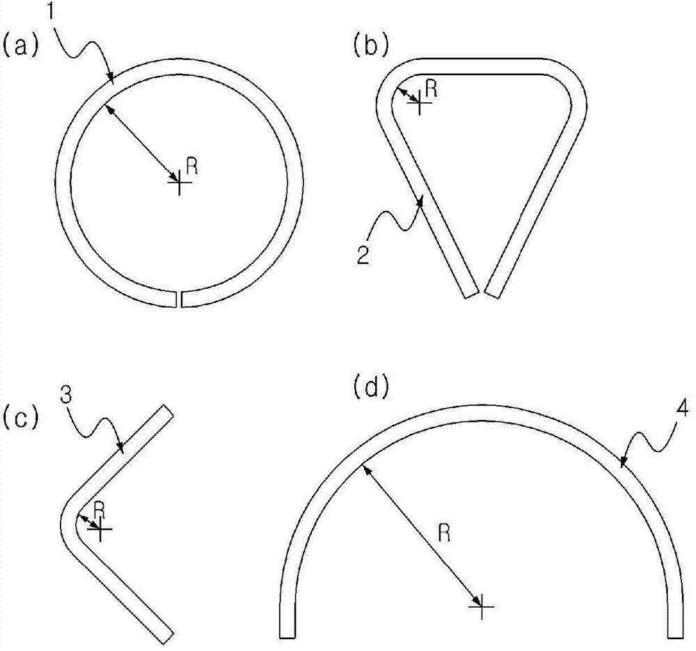
[0057] figure 1 The shape of the unit member used to make the web material of the present invention is shown. Such as figure 1 As shown, the web material of the composite beam of the present invention is made of unit members having a circle 1, a heart 2, an inequality 3, and a semicircle 4, which are bent with a predetermined radius R, so as to be manufactured at certain intervals with multiple Patterned web material.

[0058] figure 2 Showing the cross-sectional shape of the unit member of the present invention, it is formed as a cross-section of a circular steel pipe, a square pipe, or a rolled steel (H-shaped steel, C-shaped steel) with minimal change in material properties due to bending.

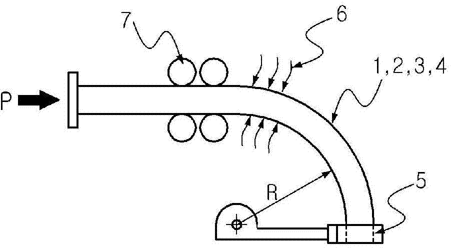
[0059] image 3 is a schematic view showing an apparatus for producing a unit member of the present ...


PUM


Abstract

The present invention relates to the development of a composite girder, comprising steel web members, a concrete lower cord member and a concrete upper floor plate. Conventional composite truss girders having a concrete lower cord member have problems to be solved such as the generation of localized large sectional force in a connection system section due to the use of a firmly coupled connection system, and problems caused by mounting a partition wall in a middle support, or the like. The present invention uses various patterns for web members instead of a conventional triangular truss structure so as to smoothly transfer force between members and to develop a composite girder bridge for converting the structure type of a main girder from a truss structure to a beam structure according to a main construction step. To this end, the composite girder of the present invention comprises: a framed structure made from a steel material of which the structural behavior is similar to a truss; a concrete lower cord member for completely surrounding the lower steel material of the framed structure; a concrete web member for filling a part of a web space of the framed structure; and a concrete floor plate coupled to the upper cord member of the framed structure. The composite girder of the present invention can appropriately utilize the advantages of the truss structure and the beam structure and the advantages of the steel material and the concrete according to construction conditions and construction steps.

Description

technical field [0001] The present invention relates to a composite beam, which is mainly characterized in that: in the composite beam structure, that is, first, a frame structure composed of only steel materials is manufactured in the factory and transported to the erection site, and then the connecting piece is cut at the manufacturing site or on the bridge pier. In the composite beam structure integrated with concrete members to resist external loads, steel pipes, square pipes, or rolled steel sections are bent to produce unit members with a predetermined shape through high-frequency heating, and then these unit members are joined by connecting plates To make web materials with various patterns, longitudinal stringers are combined on the upper and lower parts of the web materials respectively, so as to make a steel frame structure, and then the longitudinal stringers bonded to the lower part of the frame structure are combined with Concrete members with a predetermined shap...

Claims


Application Information

Patent Timeline
IPC IPC(8): E01D2/00
CPCE01D2/02E01D2/04E01D2101/268E01D2/00
Inventor 元大渊
Owner 元 大渊
Why Eureka
Try Eureka