Apparatus for treating an exhaust gas in a foreline

A vacuum pipeline and pre-stage technology, applied in mechanical equipment, exhaust treatment, discharge tubes, etc., can solve problems such as corrosion and poor dielectric tubes

Active Publication Date: 2014-12-24
APPLIED MATERIALS INC
View PDF11 Cites 3 Cited by
  • Summary
  • Abstract
  • Description
  • Claims
  • Application Information

AI Technical Summary

Problems solved by technology

However, the inventors have observed that some portions of the inner wall o

Method used


Image

  • Apparatus for treating an exhaust gas in a foreline
  • Apparatus for treating an exhaust gas in a foreline

Examples


Embodiment Construction

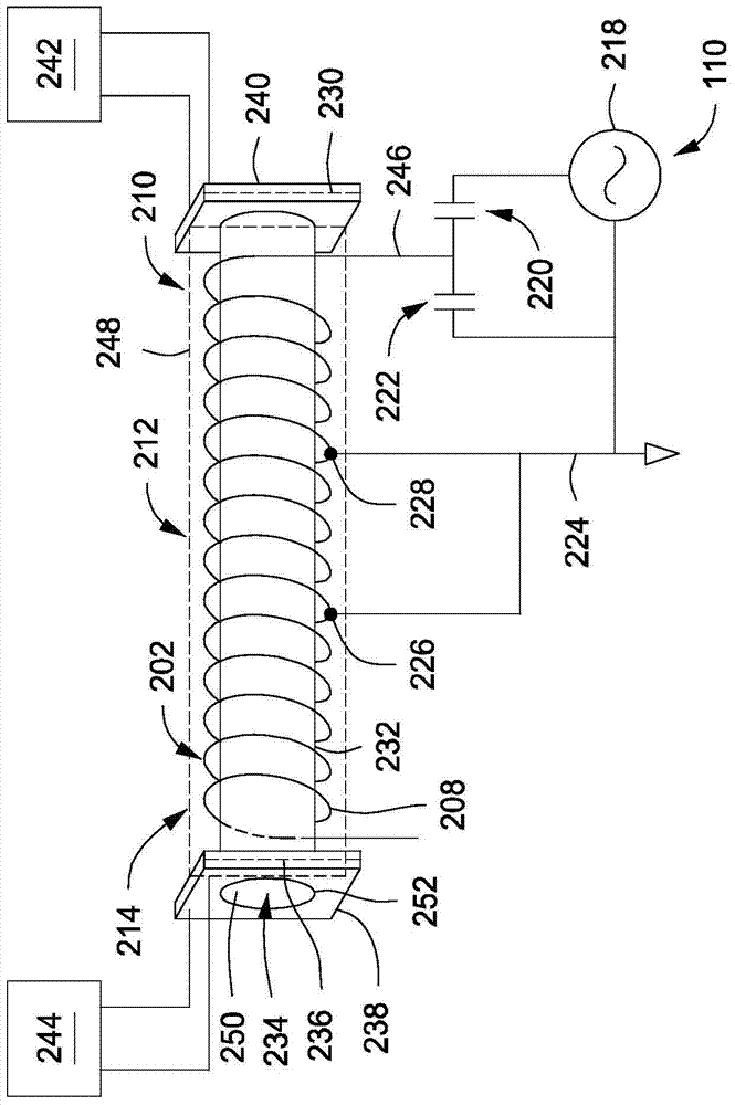
[0011] Devices for treating exhaust gases in forelines are provided here. Embodiments of the apparatus of the present invention may advantageously reduce, slow down, or eliminate corrosion of components (eg, dielectric or ceramic tubes) compared to conventional plasma-driven gas processing systems.

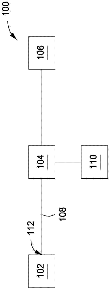
[0012] figure 1 Is a schematic illustration of a treatment system 100 suitable for use with an apparatus for treating exhaust in a backing line according to some embodiments of the present invention. The processing system 100 generally includes a processing chamber 102, a foreline 108 coupled to the processing chamber 102, and an apparatus 104 for treating exhaust gas coupled to the foreline.

[0013] The processing chamber 102 may be any processing chamber suitable for performing processing on a substrate. In some embodiments, the processing chamber 102 may be part of a processing tool, such as a cluster tool, an in-line processing tool, or the like. Non-limiting examples of s...


PUM


Abstract

In some embodiments an apparatus for treating an exhaust gas in a foreline of a substrate processing system may include a dielectric tube configured to be coupled to the foreline of the substrate processing system to allow a flow of exhaust gases from the foreline through the dielectric tube; an RF coil wound about an outer surface of the dielectric tube, the RF coil having a first end to provide an RF input to the RF coil, the first end of the RF coil disposed proximate a first end of the dielectric tube and a second end disposed proximate a second end of the dielectric tube; a tap coupled to the RF coil to provide an RF return path, the tap disposed between the first end of the dielectric tube and a central portion of the dielectric tube.

Description

technical field [0001] Embodiments of the invention generally relate to substrate processing equipment. Background technique [0002] Some exhaust gas treatment systems use radio frequency (RF) energy supplied to a central portion of a radio frequency coil located near the dielectric tube to facilitate ignition of the exhaust gas flowing through the dielectric tube to form a plasma. However, the inventors have observed that some portions of the inner wall of the dielectric tube may develop undesirable corrosion conditions over time. [0003] Accordingly, the present inventors provide an improved exhaust gas treatment system for treating process exhaust gases in the foreline. Contents of the invention [0004] An apparatus for treating exhaust gas in a foreline of a substrate processing system is provided herein. In some embodiments, an apparatus for treating exhaust in a foreline of a substrate processing system may include a dielectric tube configured to be coupled to t...

Claims


Application Information

Patent Timeline
IPC IPC(8): H05H1/46H01L21/3065H01L21/205
CPCH01J37/32834H05H1/46H01J37/32844Y02C20/30F01N3/0275F01N2240/28H05H1/4652H05H2245/17H05B6/36
Inventor 迈克尔·S·考克斯科林·约翰·迪金森
Owner APPLIED MATERIALS INC
Why Eureka
Try Eureka