Multifunctional processing equipment for substrates

A kind of processing equipment and multi-functional technology, which is applied to the device for coating liquid on the surface, pretreatment surface, coating, etc., can solve the problems of low purification degree, inability to arrange, and inability to arrange hot plates, etc., to avoid temperature fluctuations Uniformity, improvement of product quality, and diversification of processing methods

Active Publication Date: 2014-12-31
LINGDI EQUIP
View PDF5 Cites 3 Cited by
  • Summary
  • Abstract
  • Description
  • Claims
  • Application Information

AI Technical Summary

Problems solved by technology

[0004] (1) Due to the large distance from the IR lamp to the conveyor belt, the heating is performed in the form of thermal radiation, and the heat conversion rate of the IR lamp is poor, resulting in serious power loss, which undoubtedly increases the processing cost;
[0005] (2) Since the cured product is placed on the conveyor belt for transmission, its transmission must rely on the friction between the product to be cured and the conveyor belt. The friction between the cured product and the conveyor belt produces dust, although a very small amount, but It will still cause pollution of the cured product, and the degree of purification is not high;
[0006] (3) The attenuation of the IR lamp is faster, resulting in higher maintenance costs;
[0007] (4) IR lamps are used for heating, and the heating of each part of the cured product is not uniform enough, resulting in a decline in the curing quality of the product;
[0008] (5) The temperature of each IR lamp is uncontrollable, and it is difficult to meet the process requirements of some products, resulting in a decline in the curing quality of the product
[0013] It can be seen from the specific structure of

Method used


Image

  • Multifunctional processing equipment for substrates
  • Multifunctional processing equipment for substrates
  • Multifunctional processing equipment for substrates

Examples


Embodiment Construction

[0032] Further description will be given below in conjunction with the accompanying drawings and preferred embodiments of the present invention.

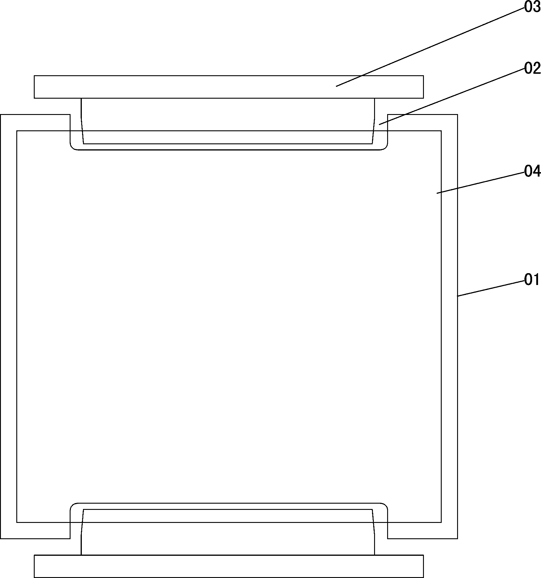
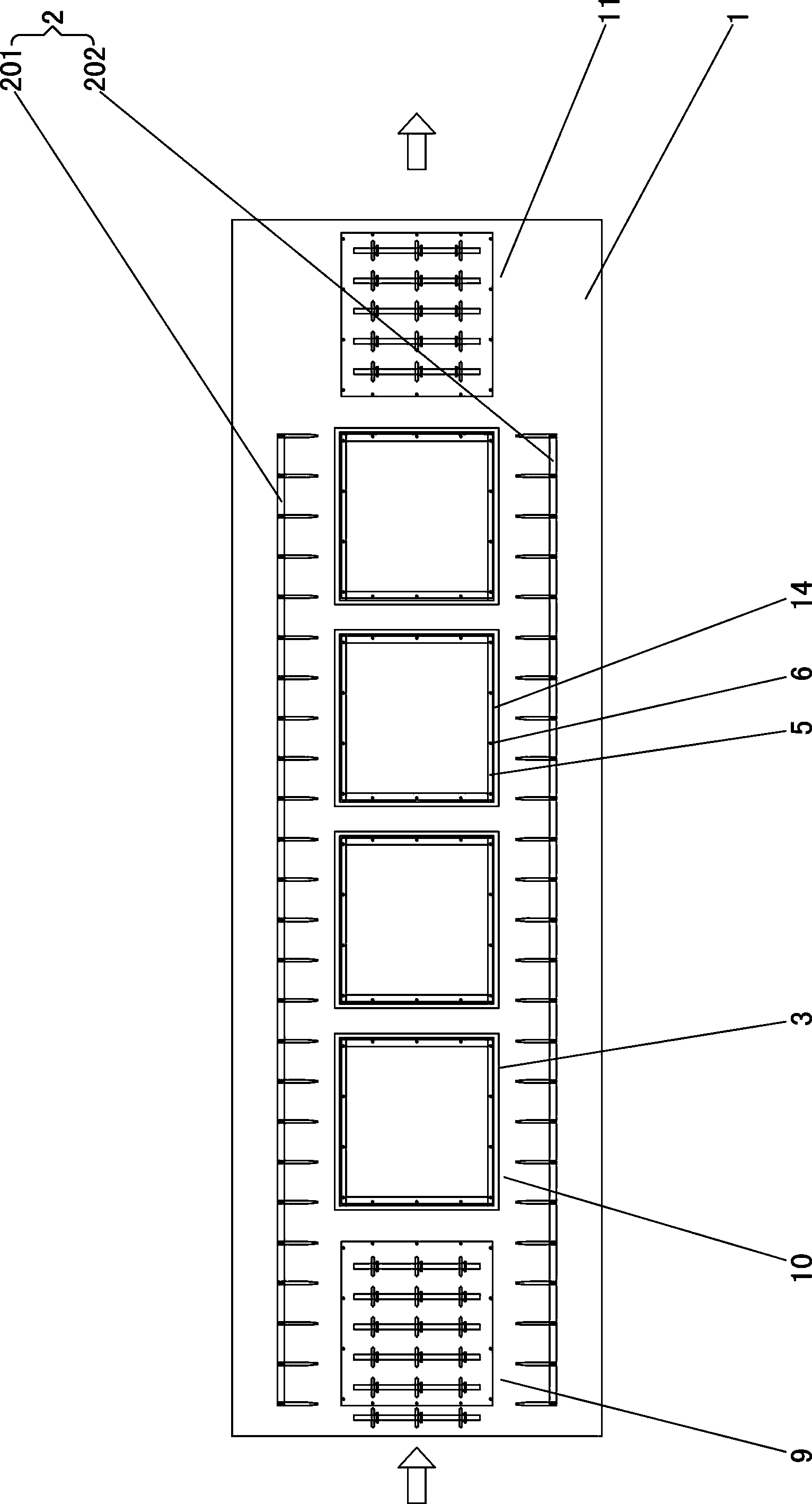
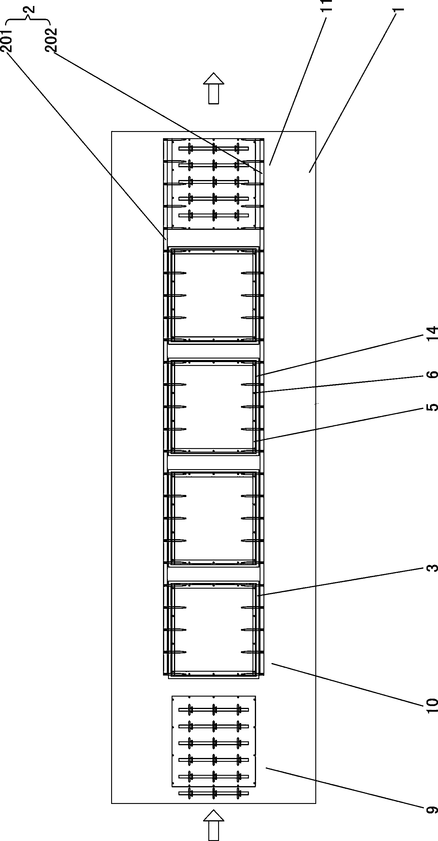
[0033] Such as figure 2 , image 3 , Figure 4 , Figure 5 , Figure 6 and Figure 7 As shown, this multifunctional processing equipment for substrates includes a frame 1, a transport mechanism 2, a plurality of processing functional components 3, a frame lifting mechanism 4, a plurality of support frames 5, a plurality of support nails 6 and a plurality of support Rod 7, height adjustment device 8 is also provided on the support rod 7; Feeding station 9, a plurality of processing stations 10 and a discharge station 11 are arranged successively along the conveying direction on the frame 1, and a plurality of processing functional parts 3 Each processing station 10 is arranged in sequence and is on the same level; the edge of each processing function part 3 is provided with a plurality of through holes 12 for the support rod 7 ...


PUM


Abstract

The invention relates to multifunctional processing equipment for substrates. The multifunctional processing equipment comprises a framework, a carrying mechanism, a plurality of processing functional components, frame lifting mechanisms, a plurality of support frames and a plurality of support rods. The widths of comb-shaped carrying forks are matched with the length of a feed station and the sum of the lengths of various processing stations, and the comb-shaped carrying forks are positioned above the various processing functional components. The multifunctional processing equipment has the advantages that each comb-shaped carrying fork only can translate in two directions, and accordingly the rhythm of production and the production efficiency can be improved; lifting can be omitted in carrying procedures, and the substrates cannot be affected by vibration, so that the quality of products can be improved; the problem that comb-shaped carrying fork penetrating notches are required to be formed in existing processing functional components can be solved, and the selectable processing functional components are diversified; sufficient spaces for mounting the support rods and the support frames are available at the edges of the various functional components, accordingly, the edges of the products can be supported, problems of uneven temperatures and the like due to the fact that existing products are supported from the middles of the existing products can be solved, the quality of the products further can be improved, and increasingly fine processing requirements can be met.

Description

technical field [0001] The invention relates to a processing device, in particular to a multifunctional processing device for substrates. Background technique [0002] At present, in the CTP industry, the pre-curing of OC, photoresist, protective glue, silver paste, ink, etc., the curing of LENS ink, the curing of OGS ink, and the coating, hard film, PI, TOP, sealing ring, The pre-curing of silver dots, etc. is generally carried out by thermal curing equipment including a conveyor belt and multiple IR lamp tubes. The conveyor belt is used to transport the product to be cured, and multiple IR lamp tubes are The conveying direction is set to heat the product to be cured. [0003] There is following defect in above-mentioned thermosetting equipment: [0004] (1) Due to the large distance from the IR lamp to the conveyor belt, the heating is performed in the form of thermal radiation, and the heat conversion rate of the IR lamp is poor, resulting in serious power loss, which u...

Claims


Application Information

Patent Timeline
IPC IPC(8): B05D3/00B05C13/00
Inventor 魏家华孙名伟吴礼丹
Owner LINGDI EQUIP
Why Eureka
Try Eureka