High-speed railway subgrade structure for saline soil areas

A high-speed railway and saline soil technology, applied to roads, road bottom layers, tracks, etc., can solve the problems of difficulty in construction control of asphalt sand barriers, inability to meet water seepage soil barriers, and large construction volume, and achieve construction quality Easy to guarantee, strong promotion and application value, and the effect of solving technical problems

Inactive Publication Date: 2014-12-31
CHINA RAILWAY SIYUAN SURVEY & DESIGN GRP
View PDF6 Cites 15 Cited by
  • Summary
  • Abstract
  • Description
  • Claims
  • Application Information

AI Technical Summary

Problems solved by technology

However, the excavation and replacement of the saline soil layer requires a large amount of construction work. After the excavation, qualified fillers need to be transported long distances, and there is a problem of spoil piles, which affects the environment. The capillary water barrier layer adopts permeable soil barrier layer or asphalt sand barrier layer. Saline soil areas generally lack water-permeable soil fillers, and the source of materials is difficult and the demand is large, which cannot meet the requirement of a thickness of 0.5-1.0m for water-permeable soil barriers. At the same time, there is a problem of difficulty in construction control of asphalt sand barriers; there are many measures to reduce groundwater levels Digging deep ditches on both sides requires a large project investment, and is generally suitable for areas with relatively poor groundwater, not suitable for areas with saline soil

Method used


Image

  • High-speed railway subgrade structure for saline soil areas
  • High-speed railway subgrade structure for saline soil areas
  • High-speed railway subgrade structure for saline soil areas

Examples


Embodiment Construction

[0025] The present invention will be further described in detail below in conjunction with the accompanying drawings and specific embodiments to facilitate a clear understanding of the present invention, but they do not limit the present invention.

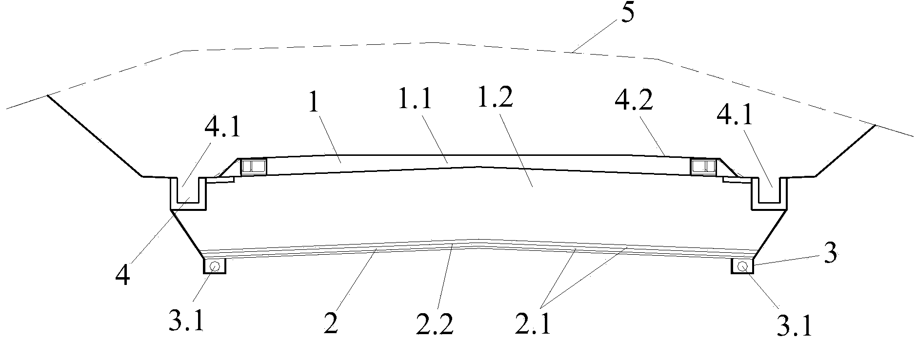
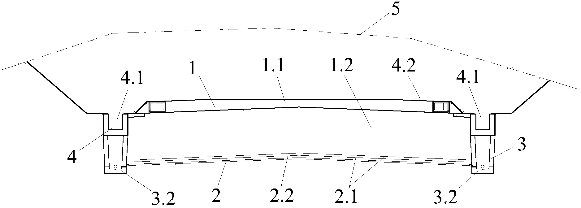
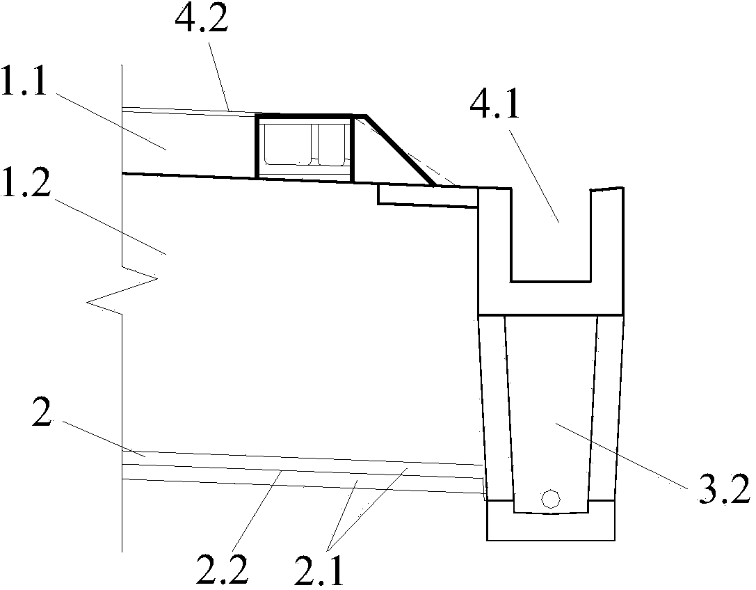
[0026] Such as Figure 1-3 As shown, the subgrade structure of the present invention is suitable for the lower terrain in the saline soil area, that is, after the subgrade structure is repaired, its top surface is lower than the original ground line 5, so it is mainly composed of cutting structure 1, partition layer 2, underground drainage System 3 and surface drainage system 4 are composed. Drainage side ditches 4.1 are arranged on both sides of the cutting structure 1, the permeable ditch 3.1 or blind drainage ditch 3.2 of the underground drainage system 3 are arranged at the lower part of the side ditch 4.1 on both sides, and the partition layer 2 is arranged at the bottom of the bottom layer 1.2 of the cutting structure bed. ...


PUM


Abstract

The invention belongs to the technical field of high-speed railway subgrade engineering, and particularly relates to a high-speed railway subgrade structure for saline soil areas. The high-speed railway subgrade structure comprises a road cutting structure, wherein the road cutting structure comprises a subgrade bed surface layer and a subgrade bed bottom layer; a partition layer is arranged at the bottom of the subgrade bed bottom layer; a surface drain system is arranged at each of two sides of the road cutting structure, an underground drain system is arranged at the bottom of the surface drain system; the partition layer extends outwards along two sides of the longitudinal direction to intersect the surface drain system or underground drain system. Based on the compact connection of the surface drain system, the underground drain system, the partition layer and the like with the components thereof to achieve special purposes, the high-speed railway subgrade structure is simple, and can effectively cut off capillary water migration pathways between subgrade soil and the road cutting subgrade bed structure, thereby avoiding the problems of salt expansion, break-up expansion, melt sinking and the like and guaranteeing the long-term normal use of high-speed railway subgrade engineering.

Description

technical field [0001] The invention belongs to the technical field of high-speed railway subgrade engineering, and in particular relates to a high-speed railway subgrade structure in saline soil areas. Background technique [0002] Saline soil refers to the soil containing more than a certain amount of soluble salt in the soil. It is a special soil with environmental sensitivity. Under the conditions of changes in environmental factors such as surface water, groundwater, and temperature, saline soil will produce salt. Therefore, when building high-speed railways in saline soil areas, it is very easy to bring adverse effects on subgrade engineering. The specification clearly stipulates that the subgrade of the saline soil section should be selected to pass through the section with high terrain, low groundwater level, good drainage conditions or relatively low salt content in the soil, and should pass through the embankment. When passing through the road cutting, disease pre...

Claims


Application Information

Patent Timeline
Patent Type & Authority Applications(China)
IPC IPC(8): E01B2/00E01F5/00
Inventor 詹学启张占荣赵新益邬强李玉良杨松蒋道君
Owner CHINA RAILWAY SIYUAN SURVEY & DESIGN GRP
Why Eureka
Try Eureka