Full-waveform digital detection device

A detection device and full waveform technology, applied in radio wave measurement systems, instruments, etc., can solve the problems of high cost, complex circuit, large volume, etc., and achieve the effect of small volume, high integration, and small amount of data

Inactive Publication Date: 2014-12-31
HANGZHOU ZHONGKE TIANWEI TECH
View PDF4 Cites 9 Cited by
  • Summary
  • Abstract
  • Description
  • Claims
  • Application Information

AI Technical Summary

Problems solved by technology

Since the width of the laser echo pulse is generally between tens and hundreds of nanoseconds, according to the sampling theorem, in order to restore the waveform, the sampling frequency of the A/D sampling circuit needs to reach hundreds of megahertz or

Method used


Image

  • Full-waveform digital detection device
  • Full-waveform digital detection device
  • Full-waveform digital detection device

Examples


Embodiment Construction

[0029] The present invention will be further described below in conjunction with the accompanying drawings and a specific embodiment of the present invention. But it should not limit the protection scope of the present invention.

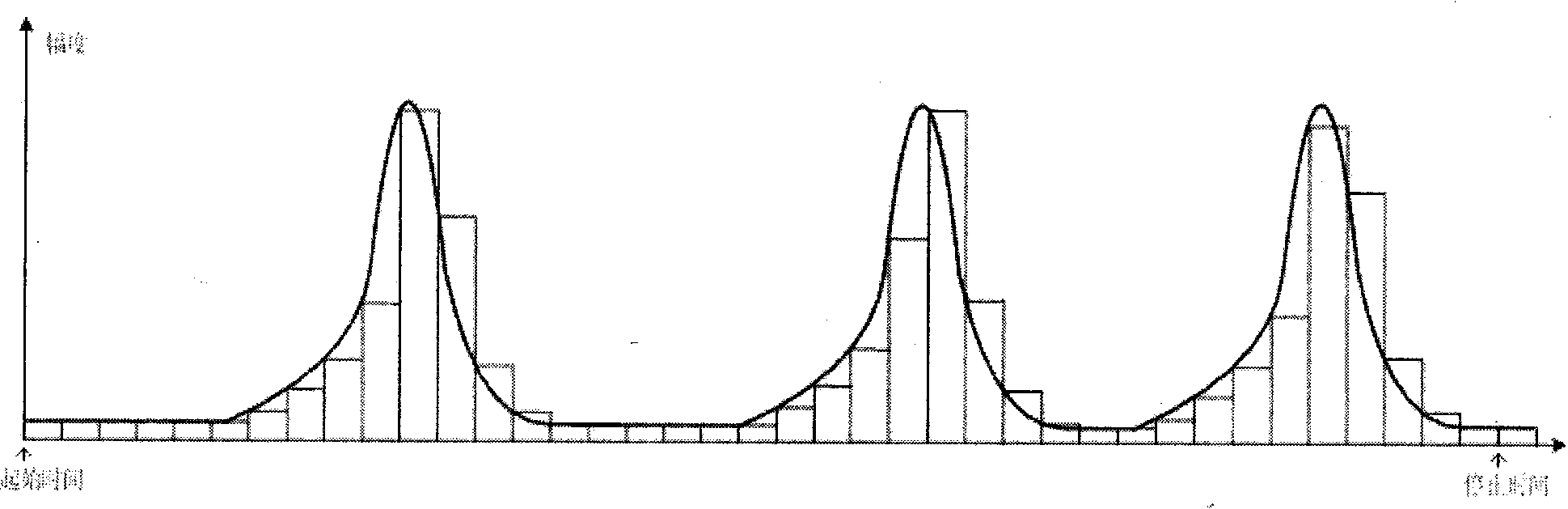
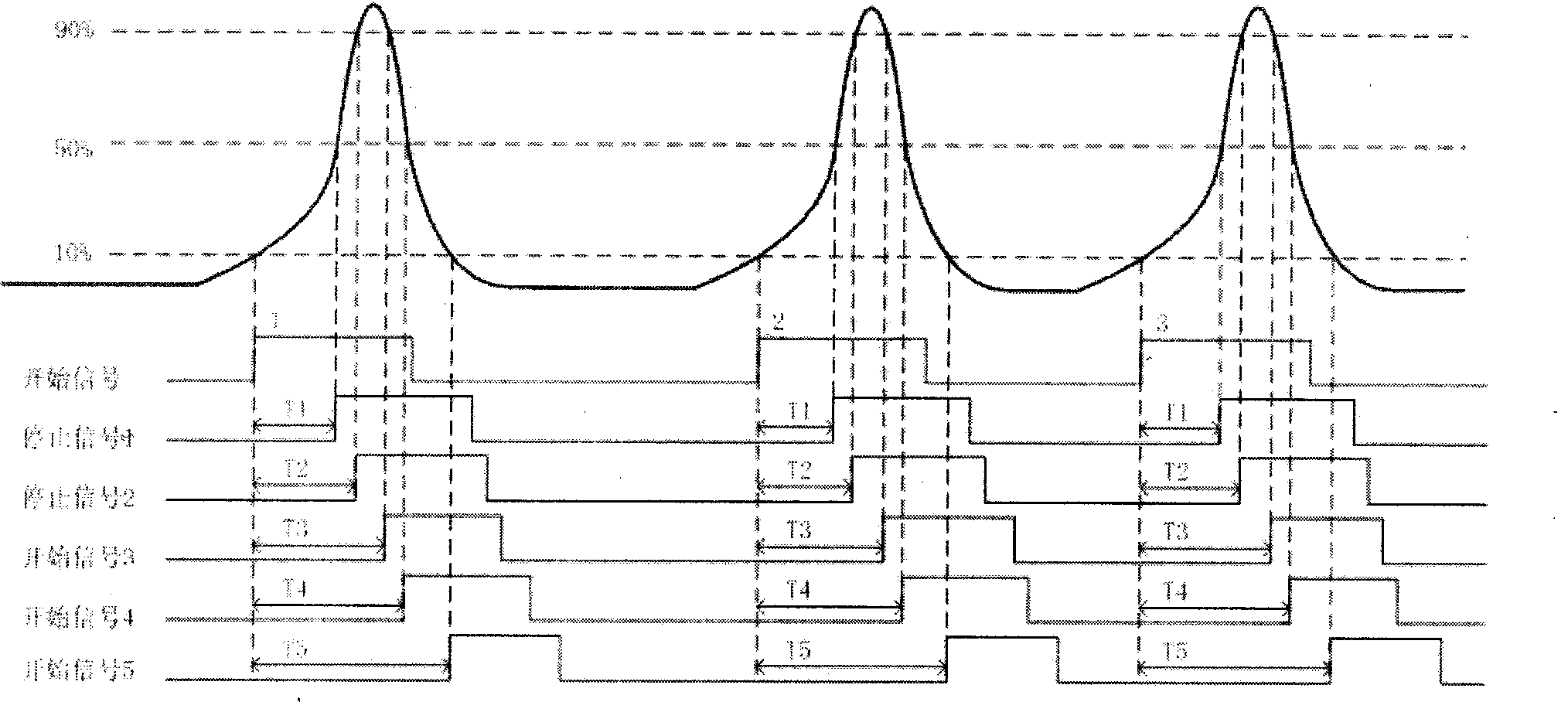
[0030] refer to figure 2 , figure 2 It is the working principle diagram of the full waveform digital detection device. In this embodiment, N=3, and the measurement of the pulse shape is converted into the measurement of five time intervals, which are respectively the time corresponding to the 10% peak voltage of the pulse front and the 50% peak value of the pulse front The time interval T1 between the moments corresponding to the voltage, the time interval T2 between the moment corresponding to the 10% peak voltage of the pulse leading edge and the moment corresponding to the 90% peak voltage of the pulse leading edge, the time interval T2 between the moment corresponding to the 10% peak voltage of the pulse leading edge and the pulse trailing ed...


PUM


Abstract

The invention relates to a full-waveform digital detection device comprising a constant fraction timing module, a time digital conversion module, a data interface module and a data storage module. A leading-edge discriminator set and a lagging-edge discriminator set of the constant fraction timing module discriminates that amplitude ratio of voltage, at pulse leading edge and pulse lagging edge, and peak voltage is a series of point corresponding moments of certain values. By integrating the digital counting method and digital delay line interpolation method, the time digital conversion module converts time intervals between the first time and each of the rest time into digital values so as to acquire data, then the data is sent to the data storage module through the data interface module. Implementation of the time digital conversion module and the data interface module is facilitated on an FPGA (field programmable gate array). The full-waveform digital detection device has the advantages such as high precision, integration and low cost and is applicable to the three-dimensional imaging laser scanner.

Description

1. Technical field [0001] The invention relates to a full waveform digitized detection technology, in particular to a method for converting pulse waveform information into digital quantities of time intervals between a series of moments in which the ratio of the pulse amplitude to the pulse peak value is a constant value. 2. Background technology [0002] As a non-contact active measurement system, 3D imaging laser scanner is widely used in urban 3D model reconstruction, construction engineering, power grid engineering, highway tunnel measurement, forest detection, cultural relics protection and other fields. At present, the 3D imaging laser scanner mainly obtains the 3D point cloud data of the measured object by the pulse time-of-flight ranging method. High point cloud density, and the amplitude and width information of the echo can be obtained, so as to obtain the surface characteristics of the target, which can greatly improve the detection ability and scene applicability...

Claims


Application Information

Patent Timeline
IPC IPC(8): G01S7/48
CPCG01S7/4804
Inventor 雷琳君贺岩王彦昌
Owner HANGZHOU ZHONGKE TIANWEI TECH
Why Eureka
Try Eureka