
Artificial surface plasmon field strength enhancer

An artificial surface, plasma field technology, applied in waveguide-type devices, electrical components, waveguides, etc., can solve problems such as no longer applicable, and achieve the effect of large field strength enhancement coefficient, expansion of application scope, and strong innovation

Inactive Publication Date: 2014-12-31
NANJING UNIV OF AERONAUTICS & ASTRONAUTICS
View PDF2 Cites 9 Cited by
  • Summary
  • Abstract
  • Description
  • Claims
  • Application Information

AI Technical Summary

Problems solved by technology

However, considering the difference between the ultra-thin "tooth-type" plasmonic waveguide and the metal wire-type plasmonic waveguide to transmit the electromagnetic field, the above scheme will no longer be applicable

Method used


Image

  • Artificial surface plasmon field strength enhancer
  • Artificial surface plasmon field strength enhancer
  • Artificial surface plasmon field strength enhancer

Examples


Embodiment 1

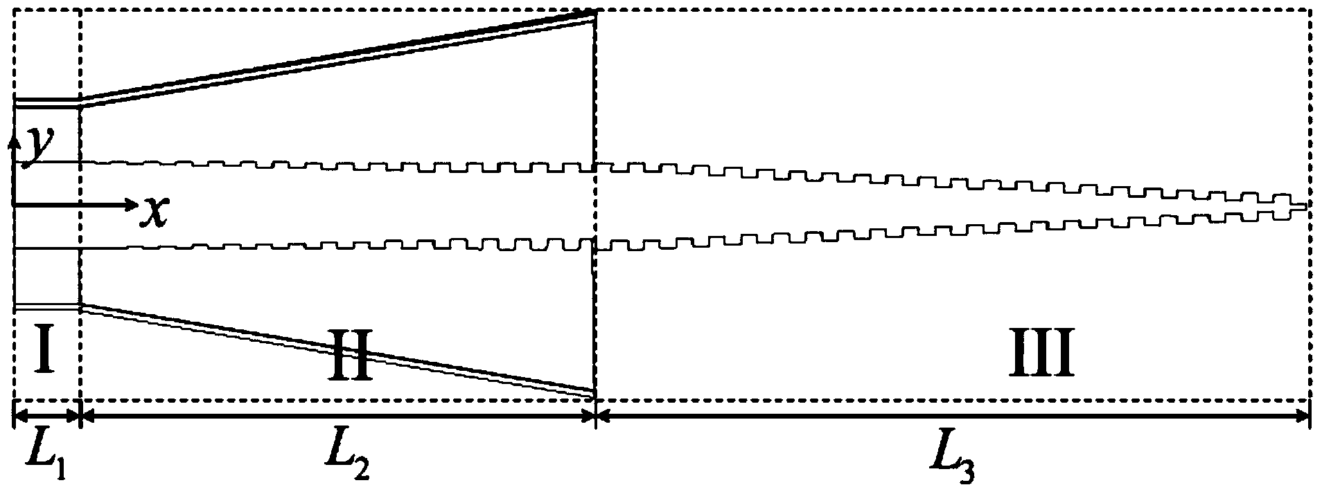
[0025] Such as figure 1 , Figure 2 (a) shows that the field booster consists of three parts. Area I is a traditional coaxial waveguide, which is used as the input end of the signal; Area II is a transitional waveguide, including the transition between the inner conductor and the outer conductor. The gradually enlarged horn antenna is realized; the area III is a conical plasmonic waveguide, which is composed of an array of circular grooves with constant depth and width, decreasing radius, and periodic changes. The structural size parameters of the transition waveguide and the conical ion waveguide are adjusted according to the type and size of the coaxial waveguide, and match the coaxial waveguide parameters (such as waveguide type, waveguide length, waveguide cross-sectional size, etc.).

Embodiment 2

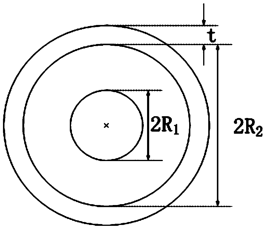
[0027] Taking the structure shown in Figure 2(b) as an example, area I is a traditional coaxial waveguide, and the single total length L 1 =200 microns, the outer diameter of the inner conductor of the waveguide is 2R 1 =280 microns, the inner diameter of the outer conductor is 2R 2 = 644 microns, wall thickness t = 10 microns. The coaxial waveguide is used as the input end of the guided wave signal.

[0028] The transition waveguide is connected with the coaxial waveguide to efficiently convert signals into SSPPs signals. As shown in Fig. 2(c), the transitional waveguide region II includes inner conductor and outer conductor transitions. The gradient depth of inner conductor transition annular groove array is from h 1 = 2.5 microns gradually increase to h according to the step size Δh = 2.5 microns 2 = 30 microns, the remainder of the annular groove array maintains the final depth h of the gradient 2 , used to achieve wavenumber matching between the coaxial waveguide an...


PUM


Abstract

The invention provides an artificial surface plasmon field strength enhancer, which comprises a traditional coaxial waveguide, a transition waveguide from the coaxial waveguide to an artificial surface plasmon waveguide, and a conical plasmon waveguide, wherein the transition waveguide comprises inner conductor and outer conductor transition, and the inner conductor transition is realized by a depth-increasing periodic annular groove array; the outer conductor transition is realized by a horn antenna with a gradually increased opening, and the conical plasmon waveguide consists of an annular groove array with constant depth and width, decreasing radius, and changeable period. The artificial surface plasmon field strength enhancer provided by the invention has the advantages of simple structure, compact size, efficient wideband, and high field strength enhancement multiples, is suitable for being matched with the traditional microwave or terahertz transmission circuit for use, and can be widely applied to the fields of microwave or terahertz imaging, high-resolution medicine endoscope technology, bio-detection, national security, food and agricultural product quality control, global environmental monitoring and information and radar communication technology and the like.

Description

technical field [0001] The invention relates to a structure of a field strength enhancer, in particular to a structure of an artificial surface plasma field strength enhancer. Background technique [0002] In recent years, it has been proposed to dig holes or grooves in the metal surface to increase the penetration of electromagnetic fields in the metal, so that SPPs can be engineered at lower frequencies. Such surface plasmons whose plasma frequency is controlled by the surface geometry are called artificial surface plasmons (Spoof Surface Plasmon Polaritons, SSPPs for short). The basic idea is to dig periodically distributed holes on the metal surface. The size and interval of the holes are smaller than the wavelength to enhance the penetration of electromagnetic waves, thereby reducing the plasma frequency of the metal surface by means of an equivalent medium. In 2005, Hibbins et al. confirmed the phenomenon of SSPPs in the microwave range, and since then SSPPs have arou...

Claims


Application Information

Patent Timeline
IPC IPC(8): H01P5/08H01P3/10
Inventor 刘亮亮李茁陈晨顾长青许秉正宁苹苹
Owner NANJING UNIV OF AERONAUTICS & ASTRONAUTICS
Learn More