
High-pressure stratification and spark ignition device for an internal combustion engine

A spark ignition, internal combustion engine technology, applied in spark ignition controllers, mechanical equipment, engine ignition, etc., can solve problems such as reducing filling capacity, reducing overall efficiency, and delaying the start of ignition, reducing fuel consumption and consumption. , Increase the effect of producing Chenben

Inactive Publication Date: 2014-12-31
维亚内·拉比
View PDF6 Cites 10 Cited by
  • Summary
  • Abstract
  • Description
  • Claims
  • Application Information

AI Technical Summary

Problems solved by technology

However, both arrangements quickly reach their limits in improving the efficiency of controlled-ignition reciprocating internal combustion heat engines
[0013] This is because increasing the temperature of the combustion chamber walls of a reciprocating internal combustion heat engine has the disadvantage of reducing its filling capacity: the cold air or gas mixture that gets in contact with said hot walls immediately expands, thereby reducing the volumetric efficiency of said engine during the intake phase , thus reducing its overall efficiency
[0036] However, the problem with squish chambers is that the piston must be brought very close to the cylinder head with the attendant risk of collision between said piston and said cylinder head, while only providing the desired squish effect near top dead center , that is, the moment of ignition is relatively late relative to the spark-initiated ignition of the charge
[0037] Another disadvantage of the squish chamber is that it strongly promotes the heat exchange between the gas and the inner walls of the combustion chamber

Method used


Image

  • High-pressure stratification and spark ignition device for an internal combustion engine
  • High-pressure stratification and spark ignition device for an internal combustion engine
  • High-pressure stratification and spark ignition device for an internal combustion engine

Examples


Embodiment Construction

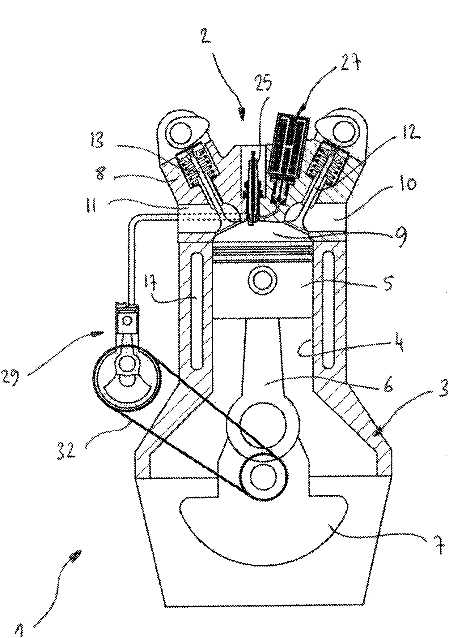
[0108] figure 1 An internal combustion engine 1 comprising a high-pressure spark ignition and stratification device 2 according to the invention is shown.

[0109] The internal combustion engine 1 comprises an engine block or crankcase 3 containing at least one combustion cylinder 4 closed by a cylinder head 8 and in which cylinder a combustion piston 5 moves.

[0110] The combustion piston 5 is articulated on a connecting rod 6 connected to a crankshaft 7 which transmits the movement of the combustion piston 5 to the crankshaft 7 as it moves within the combustion cylinder 4 .

[0111] The cylinder head 8 of the internal combustion engine 1 comprises a combustion chamber 9 into which, on the one hand, there is an intake duct 11 , which may or may not be closed by an intake valve 13 , and which communicates with an intake plenum 19 , and on the other hand , there is an exhaust duct 10 leading therein which may or may not be closed by an exhaust valve 12 and which communicates ...


PUM


Abstract

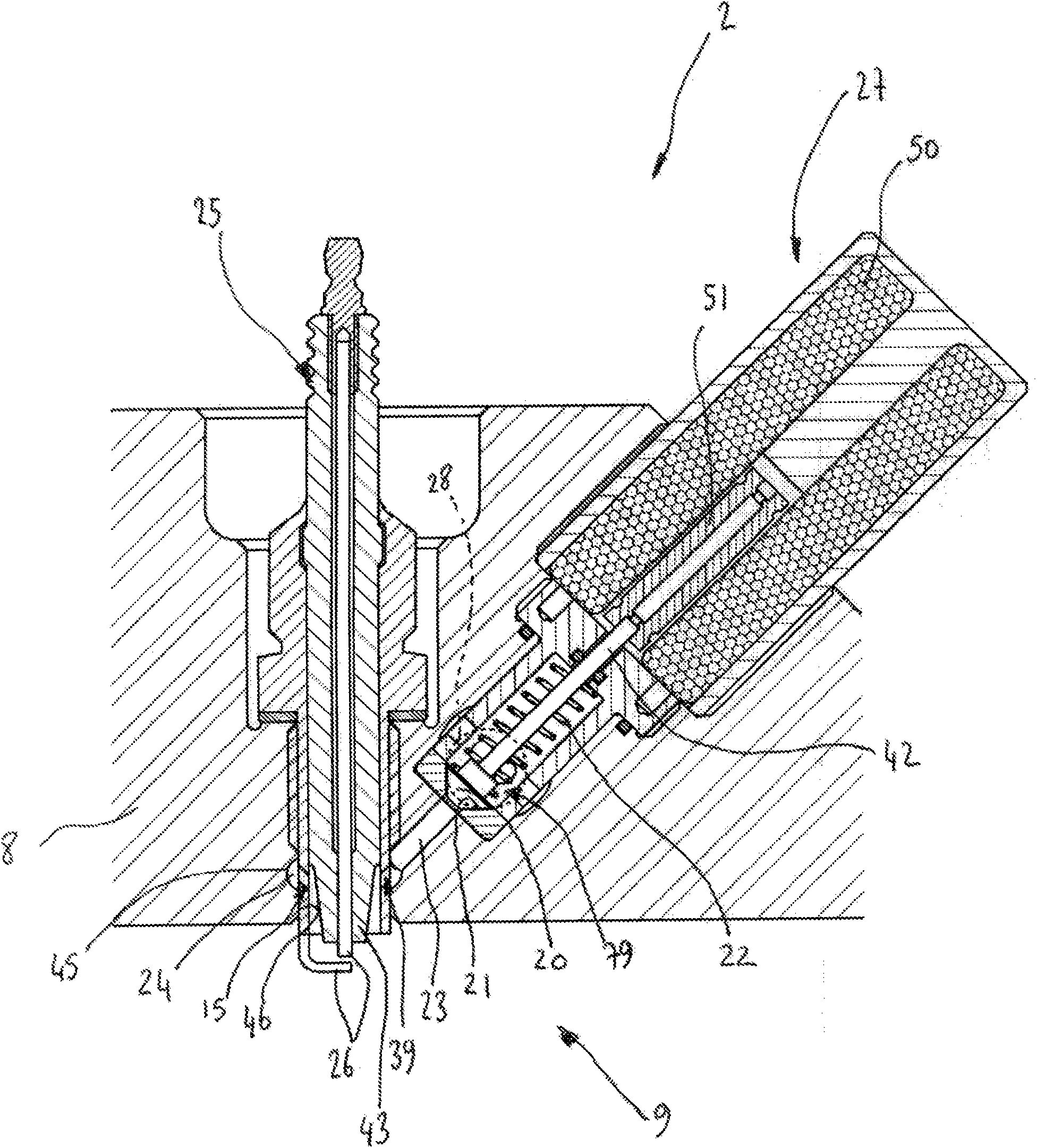
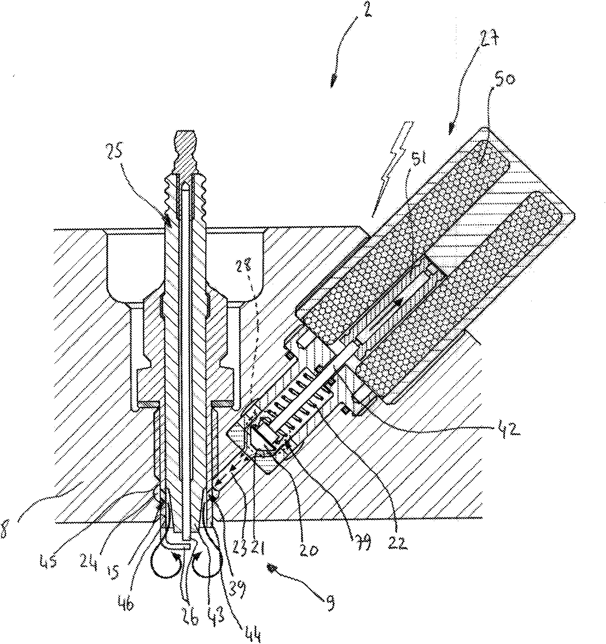
The present invention relates to a high-pressure stratification and spark ignition device (2) for an internal combustion engine (1), including: a stratification valve (20) closing a stratification channel (23) that leads into a stratification antechamber (79), said channel also leading into a stratification chamber (24) connected to the combustion chamber (S) of the internal combustion engine (1) via a stratification injection pipe (39), wherein said channel opens in the vicinity of protruding electrodes (26) of a spark plug (25), said electrodes being positioned in said combustion chamber; a stratification actuator (27), which lifts the stratification valve (20); a stratification manifold (28) connecting the stratification antechamber (79) to the outlet of a stratification compressor (21); a stratification fuel injector (33); and a means (40) for recirculating pre-cooled exhaust gases.

Description

technical field [0001] This invention relates to high pressure spark ignition and stratification apparatus for reciprocating internal combustion engines in which a highly diluted charge recirculates precooled exhaust gas using a device known as an "externally cooled EGR" device. Background technique [0002] The thermodynamic efficiency of a reciprocating internal combustion heat engine depends on a number of factors, including, first, the duration and phasing of the combustion designed to increase the temperature of the gases that are compressed and then collected in the combustion chamber; loss of the gas in contact with the inner walls of the engine; and thirdly, the rate of expansion of the gas which allows the gas to exert thrust on the pistons of the engine in order to convert the heat energy released by the combustion into mechanical achievement. [0003] However, the positive work produced by the thrust of the gas against the piston as it expands is partially lost b...

Claims


Application Information

Patent Timeline
IPC IPC(8): F02B19/02F02B17/00F02D13/02F02F1/24F02B23/08F02M23/00
CPCF02B1/12F02B17/00F02B19/02F02B23/08F02B29/0406F02D13/0276F02D41/0002F02D41/0065F02D41/3023F02D2041/3088F02M21/0275F02M23/003F02P15/006F02M26/05F02M26/16F02M26/28F02M26/43Y02T10/12Y02T10/30
Inventor V·拉比
Owner 维亚内·拉比
Learn More