Eureka AIR delivers breakthrough ideas for toughest innovation challenges, trusted by R&D personnel around the world.

Molecular sieve control system

A control system and molecular sieve technology, applied in filtration and separation, separation methods, dispersed particle separation, etc., can solve the problems of large power consumption, insufficient heat of molecular sieve purified gas, insufficient heat supply in the heating stage of molecular sieve, etc.

Inactive Publication Date: 2015-01-07
ELECTRON CO LTD
View PDF4 Cites 8 Cited by
  • Summary
  • Abstract
  • Description
  • Claims
  • Application Information

AI Technical Summary

Problems solved by technology

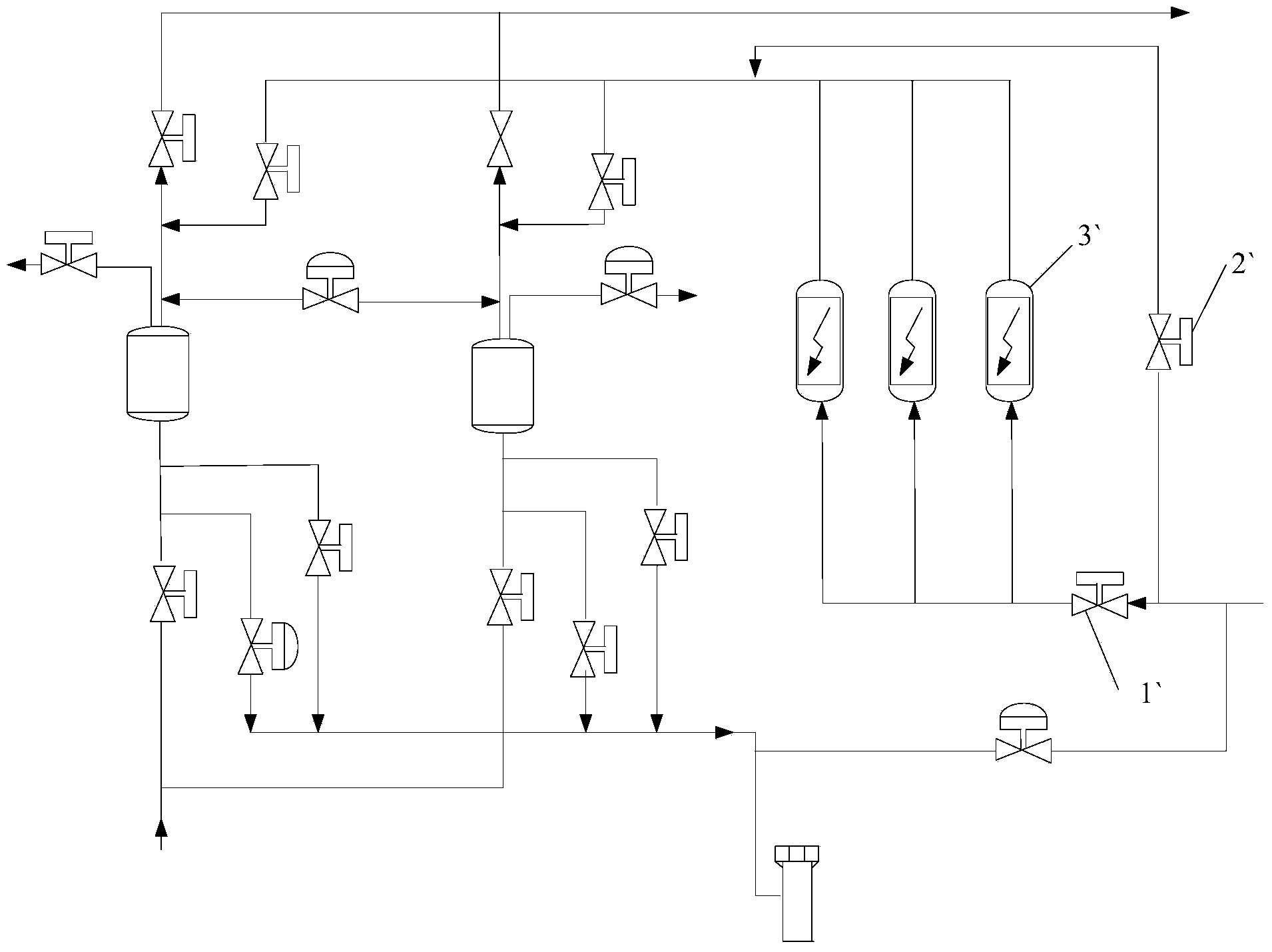
[0005] Before the contaminated nitrogen enters the molecular sieve heating stage, it first enters the molecular sieve preheating stage. Valve 1` is opened and valve 2` is closed. At this time, the molecular sieve electric heater 3` is turned on, and the preheating process of the electric heater 3` is only a short 2 minutes. Or so, its heat has not yet reached the working temperature of the dirty nitrogen gas, and after the regenerated dirty nitrogen gas flows through the electric heater 3`, it can only take away a small part of the heat, which may easily lead to insufficient heat of the molecular sieve purified gas, thus affecting the smooth regeneration If it is not handled in time, it will easily cause the interlocking shutdown of the entire air separation unit
[0006] Since the molecular sieve heating works intermittently, the power of the electric heater 3` is required to be high during work to reach the working temperature as soon as possible, and the number is required to be set to two or more, which consumes a lot of power, and the electric heater Heater 3' intermittent working mode is also a kind of waste to energy
If it is replaced with an electric heater with a lower power, it will easily lead to insufficient heat supply in the molecular sieve heating stage

Method used


Image

  • Molecular sieve control system
  • Molecular sieve control system

Examples


Embodiment Construction

[0023] The following will clearly and completely describe the technical solutions in the embodiments of the present invention with reference to the accompanying drawings in the embodiments of the present invention. Obviously, the described embodiments are only some, not all, embodiments of the present invention. Based on the embodiments of the present invention, all other embodiments obtained by persons of ordinary skill in the art without making creative efforts belong to the protection scope of the present invention.

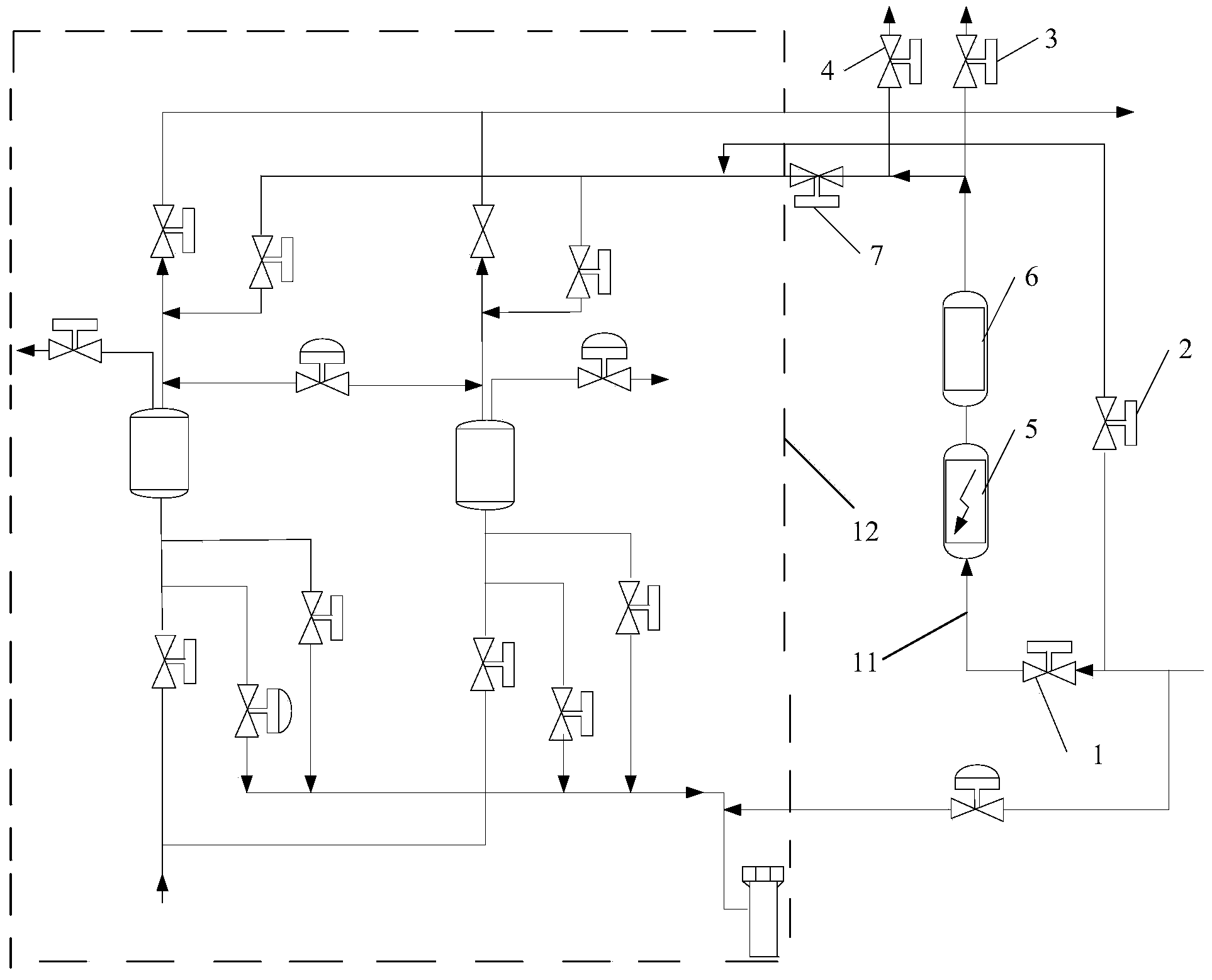
[0024] Such as figure 2 as shown, figure 2 It is a schematic diagram of the pipeline arrangement structure of the molecular sieve control system provided by the present invention.

[0025] The present invention provides a molecular sieve control system, comprising sequentially arranged molecular sieve preheating pipeline 11 and molecular sieve regeneration pipeline 12, and molecular sieve preheating pipeline 11 is sequentially arranged with an electric heat...


PUM


Abstract

The invention provides a molecular sieve control system which comprises a molecular sieve preheating pipeline and a molecular sieve regeneration pipeline which are arranged in sequence, wherein an electrical heating device and a heat storage device are arranged on the molecular sieve preheating pipeline in sequence from the inlet of the pipeline. Due to the arrangement of the heat storage device, the temperature of waste nitrogen in the molecular sieve preheating pipeline is kept in a certain range; the temperature in the molecular sieve preheating pipeline is controlled through a temperature control device, the heat storage device and the electrical heating device, heat required in a molecular sieve is replenished by the heat storage device when the molecular sieve is subjected to regenerative heating, and sufficient heat is provided for waste nitrogen during the molecular sieve preheating period, so that the situation of air separation interlocking parking easily caused by insufficient heat in the heating period is avoided.

Description

technical field [0001] The invention relates to the technical field of automatic control, and more specifically relates to a molecular sieve control system. Background technique [0002] The molecular sieve adsorber is a vertical, radial flow cylindrical container, which contains molecular sieve adsorbent and a fixed support plate at the lower end. Molecular sieve adsorbers are used to adsorb moisture, carbon dioxide and most hydrocarbons in the air. The adsorption capacity of the adsorbent for the above components has an upper limit, and must be regenerated after working for a certain period of time. The dry dirty nitrogen is heated and flowed back through the adsorbent bed to realize the regeneration of the adsorber. After the regeneration is completed, the adsorber is cooled by another normal-temperature dirty nitrogen. Because of this intermittent working mode, molecular sieve adsorbers are usually equipped with two or more. [0003] The polluted nitrogen used for re...

Claims


Application Information

Patent Timeline
IPC IPC(8): B01D53/02B01J20/34
Inventor 柳希泉李学波张国华赵成文张佳华亓子超李源孙英云陈铁军韩梦云裴常明向兆永王辉李晓峰
Owner ELECTRON CO LTD
Why Eureka
Eureka Blog
Learn More