Full penetration fillet weld back-gouging-free welding technology

A welding process and fillet weld technology, applied in the field of full penetration fillet weld root-free welding process, can solve the problems of difficult correction of distortion and deformation, lack of fusion, weakened root strength, etc., so as to improve the welding qualification rate and ensure construction. Quality, the effect of simplifying the welding process

Inactive Publication Date: 2015-01-07
CHINA SIXTH METALLURGICAL CONSTR
View PDF4 Cites 18 Cited by
  • Summary
  • Abstract
  • Description
  • Claims
  • Application Information

AI Technical Summary

Problems solved by technology

However, incomplete penetration and non-fusion defects are prone to occur during the first pass of welding; and the temperature of the carbon arc gouging root removal is above 3000 ° C, which is prone to large welding deformation; at the same time, the root strength is weakened when the root defect is removed
Under the combined effect of the above factors, plus the release of the first welding stress, it is easy to cause a large deformation of the box girder, and even lead to the distortion of the box girder.
After deformation, the amount of misalignment of adjacent joints will increase; it will affect the connection with outriggers and connecting beams, and the smooth operation of the walking mechanism, etc., and also increase the difficulty and cost of production
For this kind of large box girder, it is difficult to correct once the distortion occurs
Even if it is corrected, it is difficult to ensure that the comprehensive tolerance required by the design is met

Method used


Image

  • Full penetration fillet weld back-gouging-free welding technology
  • Full penetration fillet weld back-gouging-free welding technology
  • Full penetration fillet weld back-gouging-free welding technology

Examples


Embodiment Construction

[0023] The specific implementation manners of the present invention will be described in detail below in conjunction with the accompanying drawings.

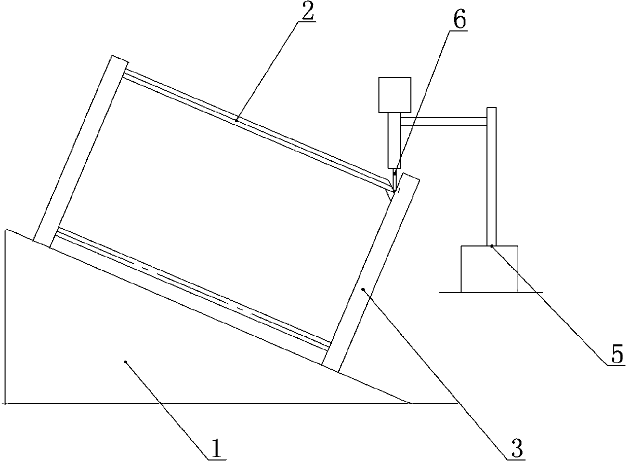
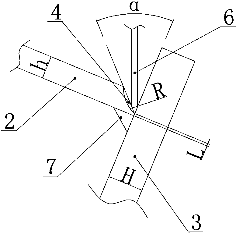
[0024] see figure 1 , figure 2 , this embodiment is the assembly and welding of a large box girder, the web thickness h is 16 mm, the wing plate thickness H is 24 mm, and the welding seam requirements are Class I welding seam requirements, and the steps adopted are as follows:

[0025] 1) Process the groove of the web 2 by planing machine (such as figure 2 ), the groove is a unilateral U-shaped groove, the groove angle α is 35°, the blunt edge L is 0-2mm, and the root arc radius R is 8mm;

[0026] 2) Make the welding tire, ensure the inclination angle of the welding tire, so that the center line of the welding wire is on the bisector of the angle between the web groove and the wing plate during welding;

[0027] 3) Place the web and wing plate tightly on the welding tire while ensuring its straightness and flatness, and pre...


PUM

PropertyMeasurementUnit
angleaaaaaaaaaa
radiusaaaaaaaaaa

Abstract

The invention belongs to the technical field of steel structure welding and provides a full penetration fillet weld back-gouging-free welding technology. The welding technology comprises the following steps of: 1) processing a groove of a web plate and decreasing the welding groove as much as possible, 2) fabricating a welding body, ensuring an inclination angle of the welding body to allow a center line of a welding wire to be located on a bisector of an included angle between the groove of the web plate and a wing plate during welding, 3) assembling and placing the web plate and the wing plate on the welding body in a push-against manner, ensuring the straightness and planeness of the web plate and the wing plate and accurately controlling focuses of the web plate and the wing plate, 4) selecting an appropriate welding wire material according to performance of a base material, and carrying out carbon dioxide gas shielded welding on a weld on the reverse side of the groove of the web plate to form a welding backing plate for later groove welding, 5) carrying out union melt welding as the first U-shaped groove welding, and 6) carrying out layered filling welding via the union melt welding, and finally carrying out cosmetic welding, wherein the groove of the web plate is a unilateral U-shaped or V-shaped groove.

Description

technical field [0001] The invention belongs to the technical field of steel structure welding, and in particular relates to a root-cleaning-free welding process for full-penetration fillet welds of thick plates. Background technique [0002] The production task of the steel structure part of large bridge erection and transportation equipment, in which the welding of the box-shaped main girder is the key in the production, its characteristics are: not only to meet the high-precision external dimensions, but also to ensure high-demand welding quality (Class I weld). [0003] The welds between the web and the flange of the box girder are T-shaped welds, which are required to meet the requirements of Class I welds. T-shaped welds often have defects such as incomplete penetration, slag inclusions, pores, cracks, etc. after welding. The common defect location is the root of the first pass weld. The conventional method to ensure the penetration of T-shaped welds is: use ship posi...

Claims


Application Information

Patent Timeline
Patent Type & Authority Applications(China)
IPC IPC(8): B23K9/18B23K9/16B23K9/235
CPCB23K9/18B23K9/02B23K9/16B23K9/235B23K33/00
Inventor 江茜王燕妮张鑫袁小平
Owner CHINA SIXTH METALLURGICAL CONSTR
Why Eureka
Try Eureka