Embossing printing plate for code printer and processing method thereof

A coding machine and layout technology, applied in the printing plate, printing plate preparation, printing process, etc., can solve the problems that affect the production efficiency, wear of the plate pattern, and the inability to find the layout position very accurately, so as to solve the problem of printing pressure inconsistency , Machining accuracy is improved, and the effect of eliminating plate loss

Active Publication Date: 2015-01-07
北京中融安全印务有限公司
View PDF10 Cites 2 Cited by
  • Summary
  • Abstract
  • Description
  • Claims
  • Application Information

AI Technical Summary

Problems solved by technology

[0006] (1) In the original printing form, due to the limitation of the thickness of the plate and the depth of the plate pattern, once the amount of ink under the ink roller is slightly larger during printing, quality problems such as ink around the plate pattern and shading are prone to occur
[0007] (2) Since the surface of the copper plate pattern is flat, not the arc surface of the corresponding printing rotation diameter, the pressure in the middle of the printed product is light, the pressure at both ends is heavy, and the fluorescence brightness value is always at the lowest limit or even fails to meet the standard
[0008] (3) When the copper plate is manually installed on the plate holder, it cannot be installed very accurately
The layout position can only take into account the top or bottom banknotes. Due to the manufacturing and installation errors, the remaining few banknotes cannot be adjusted in the left, right and circumferential directions. The layout position cannot be found very accurately, so the quality rate of the product is very high. Low
[0009] 3. Because the material of the copper plate itself is very soft, it is easy to wear the plate pattern during the printing process
It takes a long time to change the plate each time, which increases the time to find the format for the plate change and affects the production efficiency

Method used


Image

  • Embossing printing plate for code printer and processing method thereof
  • Embossing printing plate for code printer and processing method thereof
  • Embossing printing plate for code printer and processing method thereof

Examples


Embodiment 1

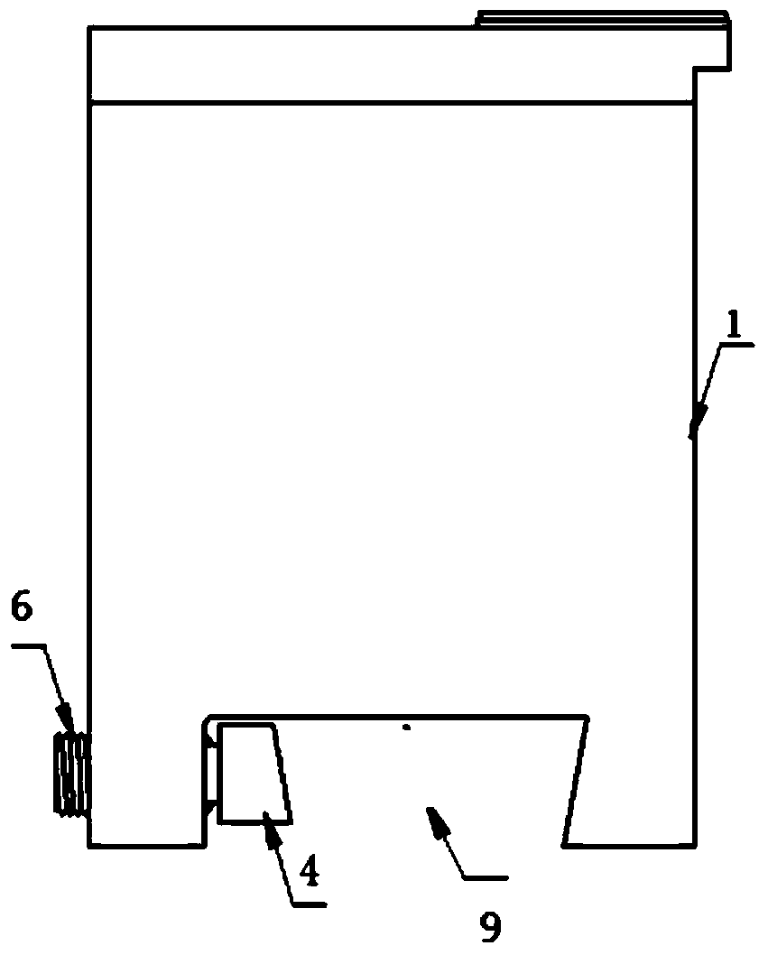
[0043] see Figure 2 ~ Figure 4 As shown, the overall structure of the relief printing plate, that is, the layout 2 and the base 1 is an integral design, which includes the layout 2 and the base 1 carrying the layout. To be installed on the printer, the arc 8 radius is 100 mm for type 300, and 137 mm for type 374. Layout 2 and base 1 are both made of 40Cr material. During the processing, the layout is heat-treated, and the base is coated with anti-seepage paint. The layout has high hardness and wear resistance, while the base has low hardness and good strength and toughness.

[0044] The inner corner of one side of the dovetail card slot 9 is a right angle, and the inner corner of the other side is an acute angle. The inner corner of the card slot is excessively rounded with a radius R of 1 mm. In addition, under the premise of not affecting the machine fluorescence and the number installation position, try to Thicken the wall thickness on both sides of the clamping, compared...

Embodiment 2

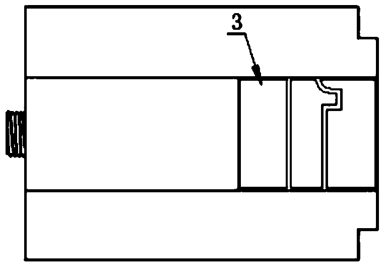
[0047] see Figure 2 ~ Figure 4As shown, the split structure relief printing plate, that is, the block 2 and the base 1 can be a split design, which includes the block 2 of the layout part and the base 1 carrying the block, and the bottom 1 of the base is provided with an arc 8 (bottom arc) and a dovetail card Groove 9 structure, in order to be installed on the printing code machine, arc radius 300 type is 100 mm, 374 type is 137 mm. The plate is made of 40Cr material, and the plate seat is made of 45 steel material. Only the plate part is heat-treated, and the plate seat part is not heat-treated. This kind of product has better manufacturability; when the machine is changing products, the plate change can be realized by changing the plate, and the plate seat does not move, so the production change is more convenient and fast.

[0048] The block height of split embossed plate is 12.5mm, and the pattern depth is >0.5mm.

Embodiment 3

[0050] The clamping structure at the dovetail slot 9 can be in two ways, see figure 2 As shown, a clamping block 4 is provided on one side of the dovetail slot, and the clamping block 4 is adjusted by a clamping screw 6 passing through the lower part of the base transversely to solve the problem of no space for side clamping. see Figure 6 As shown, the bottom of the base is provided with a clamping block 4 near the right-angle side of the dovetail slot 9, the clamping block is fixed by the clamping shaft 5, and the clamping shaft 5 is connected and fixed by the clamping screw 6 on the top of the base. This structural method can also be applied to the plate seat part of the split structure, and at the same time, it also provides an alternative method for the clamping operation of the machine.

[0051] see Figure 7-8 As shown, in order to better improve the efficiency of converting products and further reduce the cost of embossed plates, a plate wheel structure for quickly ...


PUM


Abstract

The invention discloses an embossing printing plate for a code printer and a processing method thereof. The embossing printing plate for the code printer comprises a plate surface and a bottom seat which bears the plate surface, wherein the plate surface is arranged an optional position on the bottom seat according to positions of printing patterns, the plate surface is composed of a plurality of independent embossing printing plate blocks or 2-6 squares of plate wheels, a forked tail clamp groove is formed in the lower portion of the bottom seat, a clamping block is arranged on one side of the forked tail clamp groove, the clamping block is adjusted by a clamping screw which transversely passes through the lower portion of the bottom seat, the plate surface is made of 40Cr steel and / or high carbon steel and / or alloy tool steel material, and hardness of the plate surface is improved by performing heat treatment on the plate surface during the manufacture process. The embossing printing plate for the code printer is high in production efficiency and durable. Simultaneously, the processing method of the embossing printing plate for the code printer is provided. The embossing printing plate for the code printer, produced by using the processing method, is resistant to wear and long in use life.

Description

technical field [0001] The invention relates to the field of mechanical printing, in particular to an embossed plate used for a coding machine and a processing method thereof. Background technique [0002] The original colorless fluorescent printing of RMB has always used copper plates or strips, and the materials used are copper or washed nylon. The plate-making departments of each banknote printing company usually use plate-making processes: pattern film, plate preparation, printing, corrosion, full-page and plating process. [0003] The installation method of the copper plate block or the plate strip is: fix the copper plate block on the base of the plate through 4 screws, and then clamp the dovetail card slot of the base on the seat ring of the machine, clamp and fix it; the installation method of the plate strip is: each There are 7 small patterns on the strip plate, and there are installation and fixing holes at both ends of the strip. Stretch the strip on the circula...

Claims


Application Information

Patent Timeline
Patent Type & Authority Applications(China)
IPC IPC(8): B41N1/06B41C1/00
Inventor 钱浩张惠明巩志强马海宋晓春牛汉发李炜华李春光任立军
Owner 北京中融安全印务有限公司
Why Eureka
Try Eureka