Bottle cutting device and bottle cutting method

A cutting device and cutting piece technology, applied in the field of medical equipment, can solve the problems of injury of medical staff, insufficient cutting depth, and high working intensity of medical staff, and achieve the effects of protecting personal safety, avoiding injury and reducing labor intensity.

Active Publication Date: 2015-01-07
SHENZHEN INST OF ADVANCED TECH
View PDF6 Cites 7 Cited by
  • Summary
  • Abstract
  • Description
  • Claims
  • Application Information

AI Technical Summary

Problems solved by technology

The following problems exist in the artificial preparation of medicinal liquid: it is easy to cause drug contamination and cause harm to patients; the ampoule needs to be cut, sterilized and opened before the medicinal liquid can be extracted with a syringe, and the work intensity of medical staff is high; during the process, medical staff need to contact Liquid medicine, especially when preparing toxic medicines such as tumor treatment, is likely to cause chronic injury to the dispensing personnel and cause occupational diseases; during the opening process of the ampoule bottle, it may be due to insufficient cutting depth, poor cutting edge, quality of the medicine bottle itself, etc. Broken ampoules, injuring healthcare workers
However, these automatic or semi-automatic devices also have problems, for example: the cutting process requires manual operation; the grinding wheel is prone to rigid collision at the moment of contact with the bottleneck, causing the ampoule to break and the cutting edge is not good; the cutting depth is difficult to control, and it is easy to cause subsequent bottleneck breakage fail; wait
Therefore, these automatic or semi-automatic cutting devices are still difficult to meet actual needs

Method used


Image

  • Bottle cutting device and bottle cutting method
  • Bottle cutting device and bottle cutting method
  • Bottle cutting device and bottle cutting method

Examples


Embodiment Construction

[0038] The present invention will be further described in detail below with reference to the drawings and specific embodiments.

[0039] It should be understood that although the cutting device and cutting method of the present invention are described below with reference to the cutting of ampoules, this is only an example, and the cutting device and cutting of the present invention are also suitable for cutting other objects, such as other glass bottles. It should also be understood that the cutting device and cutting method described below are only a specific embodiment of the present invention, not a limitation of the present invention; the scope of the present invention is not limited to the disclosed embodiments, and is defined by the claims.

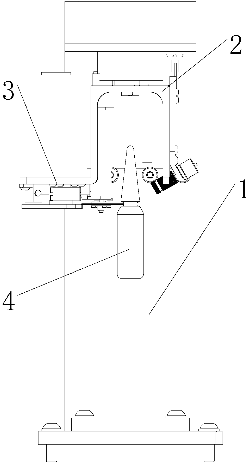
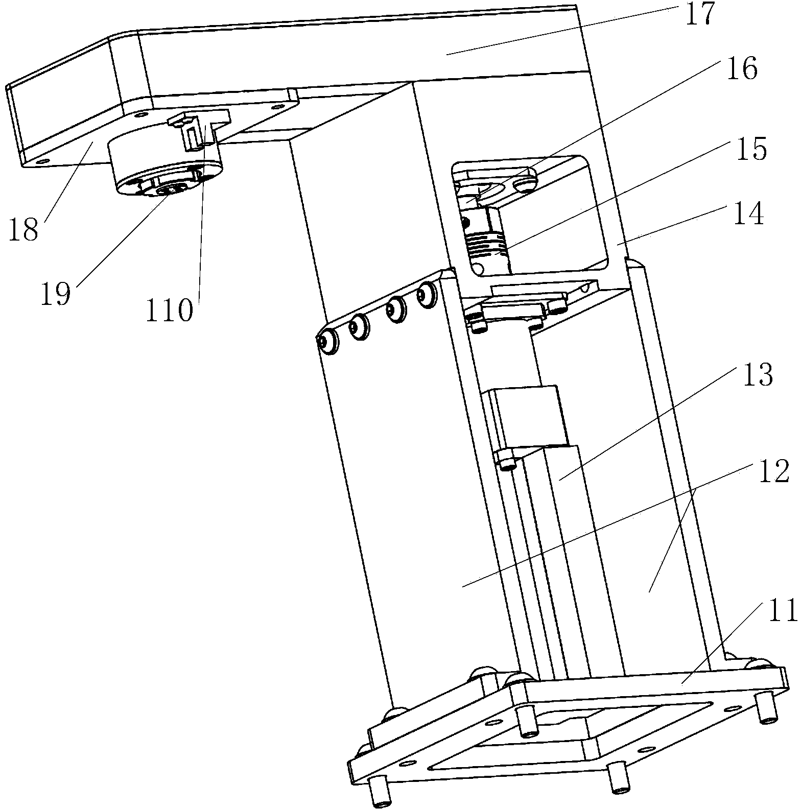
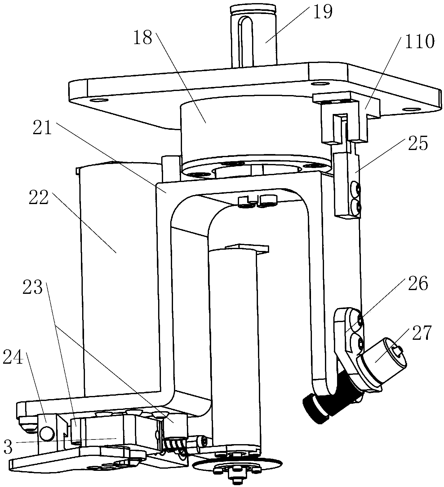
[0040] The invention relates to an automatic bottle cutting device with high cutting accuracy and economical and practicality, and is especially used in combination with machines that require automatic cutting such as a dispensing robot,...


PUM


Abstract

The invention relates to the technical field of automatic cutting, and particularly discloses a cutting device used for cutting a bottle. The bottle cutting device comprises a bracket which is provided with a first motor, a rotating unit which is rotationally connected with the bracket, is connected with the output shaft of the first motor and is provided with a second motor; a cutting unit which comprises a rotating rod rotationally connected with the rotating unit and a cutting part connected to the rotating rod, and a control unit which is connected with the motor and controls operation of the motor based on a control signal, wherein the rotating rod is connected with the output shaft of the second motor, so that the cutting part is close to or far away from the bottle on a first axial line. Cooperation of multiple motors is utilized for control, so that automatic and precise surrounding cutting for the bottle can be realized. Personal safety of a user is protected, work intensity of manpower is lightened, and damage to the bottle and risk that substances inside the bottle are polluted are avoided.

Description

Technical field [0001] The invention relates to the technical field of medical instruments, and specifically discloses a bottle cutting device and a bottle cutting method. Background technique [0002] At present, the preparation of intravenous infusion drugs in hospitals is generally done manually. The following problems exist in the manual preparation of pharmaceutical liquids: it is easy to cause drug contamination, which is harmful to patients; the ampoules need to be cut, sterilized and opened before the syringe can be used to draw the liquid medicine. The work intensity of medical staff is high; medical staff need to be in contact during the process Medicinal liquids, especially when preparing toxic drugs such as tumor treatment, are likely to cause chronic damage to the dispensing personnel and cause occupational diseases; during the opening of the ampoule, it may be due to insufficient cutting depth, poor cutting edge, and the quality of the medicine bottle itself. The a...

Claims


Application Information

Patent Timeline
Patent Type & Authority Applications(China)
IPC IPC(8): B67B7/46B67B7/92
CPCB67B7/38B67B7/92
Inventor 何玉成付雪奇胡颖张建伟
Owner SHENZHEN INST OF ADVANCED TECH
Why Eureka
Try Eureka