
Projection device

A projection device and chromatic light technology, applied in projection devices, optics, instruments, etc., can solve the problems of not being bright enough, difficult to obtain color saturation, phosphor conversion efficiency and poor color rendering, and achieve the effect of enhancing quality

Inactive Publication Date: 2015-01-07
QISDA OPTRONICS (SUZHOU) CO LTD +1
View PDF6 Cites 14 Cited by
  • Summary
  • Abstract
  • Description
  • Claims
  • Application Information

AI Technical Summary

Problems solved by technology

[0002] Whether it is a projection device or a liquid crystal screen, how to obtain a primary color light source with color purity is a very important part. However, in the past, after using colored light-emitting diodes and phosphors to emit white light, and then using filters to obtain the luminescence of each primary color light Mode, such as using blue light-emitting diodes with yellow phosphors to emit white light, may cause poor image quality due to poor conversion efficiency and color rendering of phosphors
Even with multi-color light-emitting diodes, it is not easy to obtain primary color light with high color saturation, so the displayed image may also have insufficient contrast or not bright enough.

Method used


Image

  • Projection device
  • Projection device
  • Projection device

Examples


Embodiment Construction

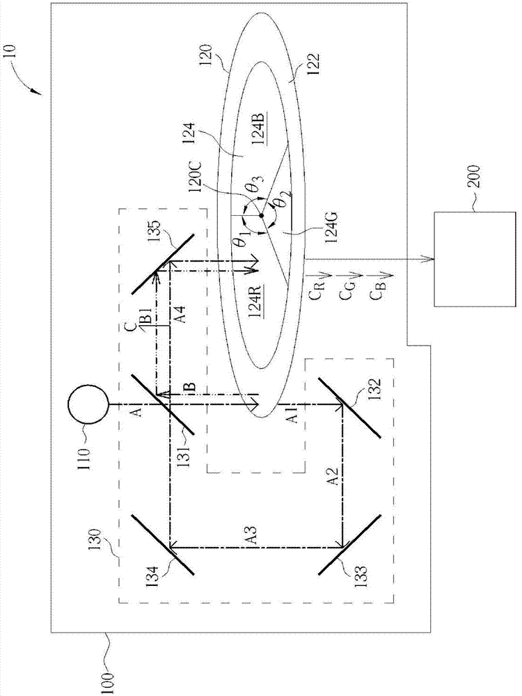
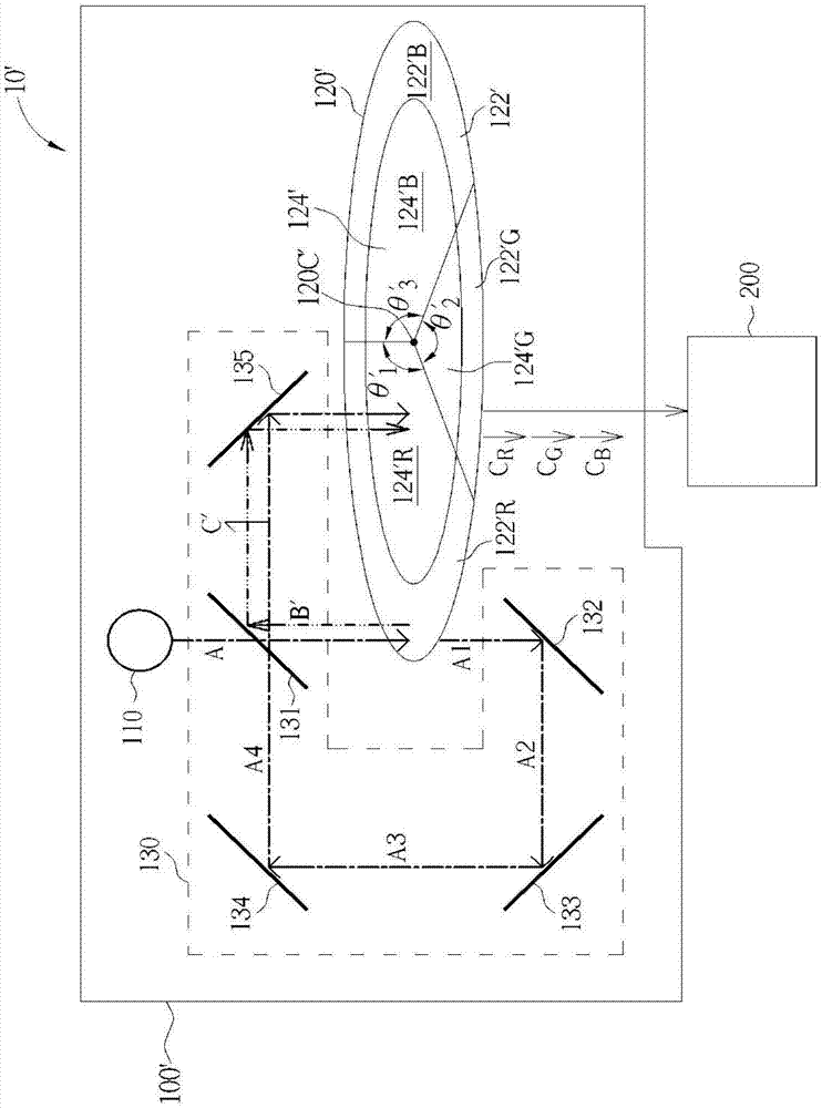
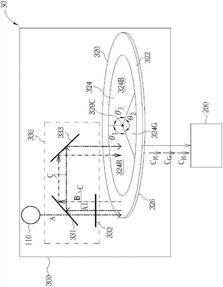
[0023] figure 1 It is a schematic diagram of a projection device 10 according to an embodiment of the present invention. The projection device 10 includes a light source module 100 and a light guide 200 . The light source module 100 includes an exciting light source 110 , a transparent disc 120 and a light splitting system 130 . The excitation light source 110 can emit excitation light. The transparent disk 120 is used for receiving the excitation light and has a center 120c. The transparent disk 120 includes a color light generating area 122 and a color wheel area 124 . A plurality of quantum dots are distributed in the colored light generating area 122 , and the quantum dots can generate stimulated light after receiving the exciting light. The color wheel area 124 is located on the transparent disk 120 and misaligned with the color light generating area 122 . The light splitting system 130 can direct the detected light emitted by the quantum dots to the color wheel area ...


PUM


Abstract

A projection device comprises a light source module and a light guide piece. The light source module comprises an excitation light source, a light transmitting disk and a beam splitting system. The excitation light source is used for emitting an excitation light beam. The light transmitting disk is used for receiving excitation light beam and comprises a colored light generating area and a color wheel area. Multiple quantum dots are distributed in the colored light generating area and are used for receiving a part of the excitation light beam so as to generate an excited light beam. The color wheel area is located in the light transmitting disk and comprises multiple light filtering areas so as to generate a plurality of colored light rays. The beam splitting system is used for guiding the excited light beam to the color wheel area. The light guiding piece is used for receiving the multiple colored light rays and transmitting the multiple colored light rays so that the multiple colored light rays can be away from the light source module.

Description

technical field [0001] The invention relates to a projection device, in particular to a projection device which utilizes quantum dots to generate received light. Background technique [0002] Whether it is a projection device or a liquid crystal screen, how to obtain a primary color light source with color purity is a very important part. However, in the past, after using colored light-emitting diodes and phosphors to emit white light, and then using filters to obtain the luminescence of each primary color light Mode, such as using blue light-emitting diodes and yellow phosphors to emit white light, may cause poor image quality due to poor conversion efficiency and color rendering of phosphors. Even with multi-color light-emitting diodes, it is not easy to obtain primary color light with high color saturation, so the displayed image may have insufficient contrast or not bright enough. [0003] Quantum dots (quantum dots, QD) are semiconductor nanoparticles. When the quantum...

Claims


Application Information

Patent Timeline
IPC IPC(8): G03B21/20
CPCG03B21/208G03B21/2033G03B21/2066
Inventor 李国骏徐坚镪
Owner QISDA OPTRONICS (SUZHOU) CO LTD
Learn More