Duty ratio correcting circuit

A duty cycle correction and duty cycle technology, which is applied in the field of signal processing, can solve the problems that the operating frequency cannot be too high, the correction result cannot be obtained, and the correction accuracy is discrete, so as to achieve strong anti-interference ability, avoid flipping and timing disorder. , the effect of suppressing temperature drift

Active Publication Date: 2015-01-07
INST OF MICROELECTRONICS CHINESE ACAD OF SCI
View PDF4 Cites 24 Cited by
  • Summary
  • Abstract
  • Description
  • Claims
  • Application Information

AI Technical Summary

Problems solved by technology

In comparison, the digital duty cycle adjustment circuit requires a complex control logic unit due to the need for matching between delay lines, and its correction accuracy is discrete, so that accurate correction results cannot be obtained, and most digital adjustment circuits use drivers and The circuit structure such as a count

Method used


Image

  • Duty ratio correcting circuit
  • Duty ratio correcting circuit
  • Duty ratio correcting circuit

Examples


Embodiment Construction

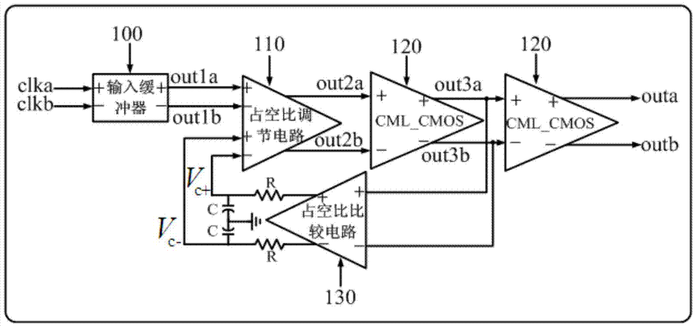
[0047] see figure 1 and image 3 , a duty ratio correction circuit provided by an embodiment of the present invention is used to adjust the duty ratio of a differential signal in real time; including:

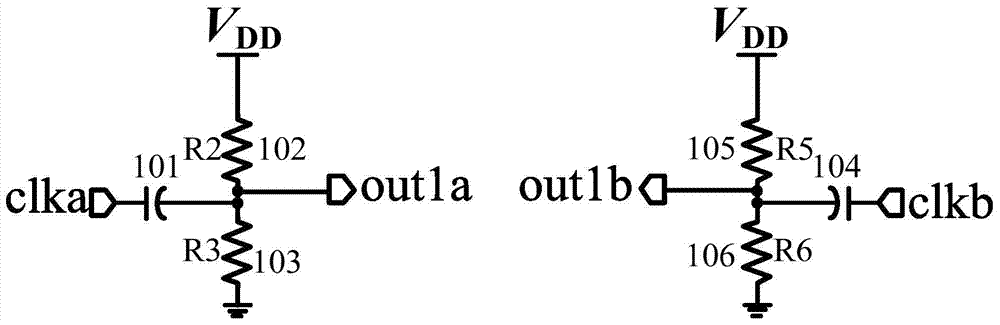
[0048] The input buffer 100 is used to receive the differential signals clka and clkb, realize the preliminary adjustment of the duty cycle of the differential signal by setting the common mode level, and output the signals out1a and out1b;

[0049] A duty cycle adjustment circuit 110, configured to receive signals out1a and out1b, adjust the duty cycle, and output signals out2ah and out2b;

[0050] The first-stage CML-to-CMOS circuit 120 is used to receive the signals out2a and out2b, amplify and shape the swing, and output the signals out3a and out3b;

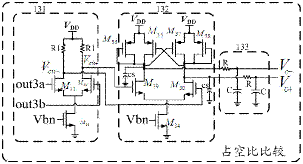
[0051] The duty cycle comparison circuit 130 receives the signals out3a and out3b, extracts the duty cycle information, amplifies and integrates the duty cycle error, and outputs the differential control voltage V c + and V...


PUM


Abstract

The invention belongs to the field of the signal processing technology, and discloses a duty ratio correcting circuit. The duty ratio correcting circuit comprises an input buffer, a duty ratio regulating circuit, a first-level CML-CMOS converting circuit and a duty ratio comparison circuit, wherein the input buffer is used for receiving a differential signal clka and a differential signal clkb, achieves initial adjustment of the duty ratio of the differential signals by setting a common mode level, and outputs a signal outla and a signal outlb, the duty ratio regulating circuit receives the signal outla and the signal outlb and outputs a signal out2a and a signal out2b, the first-level CML-CMOS converting circuit receives the signal out2a and the signal out2b, amplifies and rectifies the signal out2a and the signal out2b, and outputs a signal out3a and a signal out3b, and the duty ratio comparison circuit receives the signal out3a and the signal out3b, carries out amplification and integration on errors of the duty ratio, outputs a differential control voltage Vc+ and a differential control voltage Vc-, and feeds back the differential control voltage Vc+ and the differential control voltage Vc- to control the duty ratio regulating circuit. The duty ratio regulating circuit comprises a differential amplifier circuit and a compensation regulating unit, wherein the differential amplifier circuit amplifies the signal outla and the signal outlb, regulates the duty ratio, and outputs the regulated duty ratio to a next-level circuit, and the compensation regulating unit receives and feeds back the differential control voltages, outputs current compensation, regulates and outputs the common mode level of the signal out2a and the signal out2b and achieves feedback regulation of the duty ratio. The duty ratio correcting circuit improves correcting accuracy and efficiency.

Description

technical field [0001] The invention relates to the technical field of signal processing, in particular to a duty ratio correction circuit. Background technique [0002] With the wide application and continuous development of modern high technologies such as wireless communication, satellite positioning, remote control and telemetry technology, and precision guidance, differential signals, as important signal carriers, participate in many signal transmission systems. In addition to the traditional clock jitter, the performance of the differential signal, the duty cycle of the clock has increasingly become a key factor affecting the performance of high-speed integrated circuits. [0003] At present, commonly used duty ratio adjustment circuits can be roughly divided into two types: digital and analog. In comparison, the digital duty cycle adjustment circuit requires a complex control logic unit due to the need for matching between delay lines, and its correction accuracy is ...

Claims


Application Information

Patent Timeline
IPC IPC(8): H03K3/017
CPCH03K5/1565
Inventor 邱玉松张锋
Owner INST OF MICROELECTRONICS CHINESE ACAD OF SCI
Why Eureka
Try Eureka