CNC large engine crankshaft angle oil hole drilling rig mechanism

A crankshaft angle, engine technology, applied in the direction of boring/drilling, large fixed members, drilling/drilling equipment, etc., can solve the problems of high labor intensity of operators, low equipment efficiency, etc., to ensure automation and quality accuracy requirements, reliable product quality assurance, and the effect of improving processing efficiency

Active Publication Date: 2017-02-15
湖北伟翔数控机床股份有限公司
View PDF6 Cites 0 Cited by
  • Summary
  • Abstract
  • Description
  • Claims
  • Application Information

AI Technical Summary

Problems solved by technology

[0002] The existing crankshaft angle oil hole drilling machine is not equipped with a rotating mechanism, and all adopt the fixed angle mode of double drilling rigs, that is, the angle of the drill bit is adjusted in advance according to the requirements. The efficiency of this equipment is low, and there are defects such as high labor intensity for the operator.

Method used


Image

  • CNC large engine crankshaft angle oil hole drilling rig mechanism
  • CNC large engine crankshaft angle oil hole drilling rig mechanism
  • CNC large engine crankshaft angle oil hole drilling rig mechanism

Examples


Embodiment Construction

[0020] The present invention will be further described in detail below in conjunction with the accompanying drawings and specific embodiments to facilitate a clear understanding of the present invention, but they do not limit the present invention.

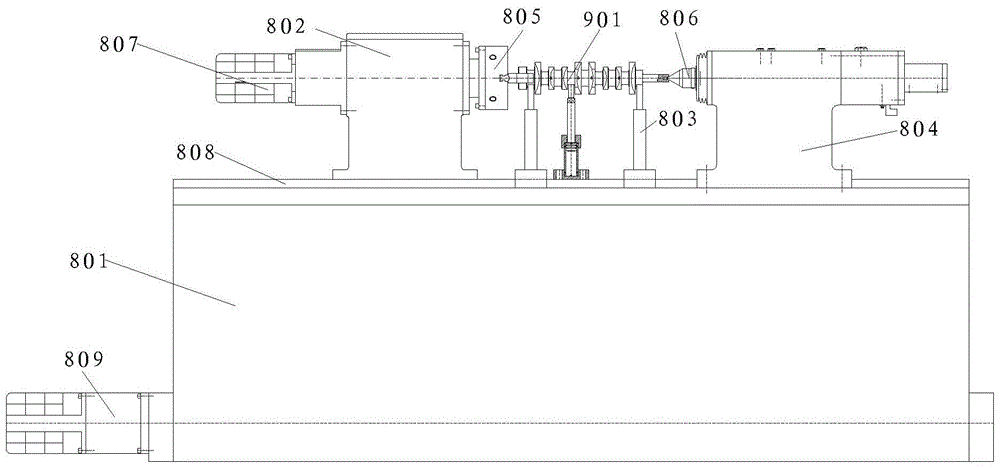
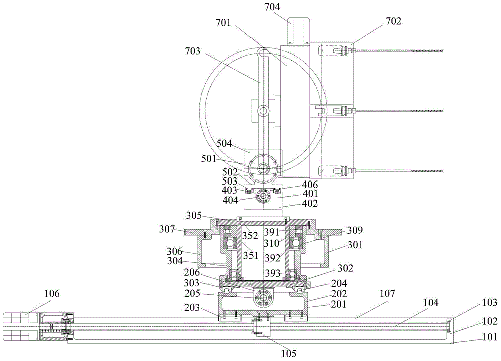
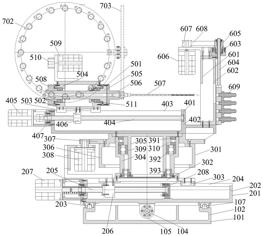
[0021] Such as figure 1 — Figure 4 As shown, the present invention includes a main frame 801 and a drill mechanism. The main frame 801 is provided with a head frame 802, a crank bracket 803 and a tail frame 804. The end of the head frame 802 is fixed with a clamp for clamping a workpiece 901. 805, the end of the tail frame 804 is provided with a top 806, the other end of the head frame 802 is connected with an eighth motor 807, the main frame 801 is provided with a fourth guide rail 808, and the head frame 802 is slidably connected to the second On the four guide rails 808, the inside of the main frame 801 is provided with a driving mechanism 809 that drives the head frame 802 to slide on the fourth guide rail 808; There is a l...


PUM


Abstract

The invention relates to a numerically-controlled drill mechanism for drilling angled oil holes in large-sized engine crankshafts and belongs to the technical field of mechanical equipment. The numerically-controlled drill mechanism comprises a main frame and a bit mechanism; the bit mechanism comprises an axial movement mechanism; a transverse movement mechanism perpendicular to the axial movement mechanism is slidably connected to the upper portion of the axial movement mechanism. A turntable mechanism is slidably connected to the upper portion of the transverse movement mechanism and comprises a turntable mounting plate with the bottom slidably connected to the transverse movement mechanism. The upper portion of the turntable mounting plate is fixedly connected with the bottom of a rotating shaft sleeve. An inner ring of the rotating shaft sleeve is movably connected with a mounting sleeve through a connection structure. An outer ring of the rotating shaft sleeve sleeves the turntable. The upper portion of the turntable is fixedly connected with the upper portion of the mounting sleeve. A rotating gear is fixed to the outside of the turntable and connected with a first motor. The turntable allows the angle of a bit to be automatically adjusted as required.

Description

technical field [0001] The invention belongs to the technical field of mechanical equipment, and in particular relates to a numerically controlled large-scale engine crankshaft angle oil hole drilling machine mechanism. Background technique [0002] The existing crankshaft angle oil hole drilling machines are not equipped with a rotating mechanism, and all adopt the fixed-angle mode of double drilling rigs, that is, the angle of the drill bit is adjusted in advance according to the requirements. The equipment has low efficiency and has defects such as high labor intensity for the operator. Contents of the invention [0003] The purpose of the present invention is to provide a numerically controlled large engine crankshaft angle oil hole drilling machine mechanism for the defects of the prior art. [0004] The technical scheme adopted by the present invention is: comprising a main frame and a drill mechanism, the main frame is provided with a head frame, a crank bracket and...

Claims


Application Information

Patent Timeline
Patent Type & Authority Patents(China)
IPC IPC(8): B23B41/00B23B47/00B23Q1/25B23Q1/01
CPCB23B41/00B23Q1/017B23Q1/25
Inventor 冯英华
Owner 湖北伟翔数控机床股份有限公司
Why Eureka
Try Eureka