
Solar medium-high-temperature loop heat pipe steam generator

A technology of a steam generator and a loop heat pipe, which is applied in the field of solar thermal utilization, can solve the problems of limited heat transfer performance, poor heat transfer performance, restrictions, etc., so as to improve stability and reliability, reduce system costs, and improve reliability. sexual effect

Active Publication Date: 2015-01-14
NANJING UNIV OF TECH
View PDF10 Cites 63 Cited by
  • Summary
  • Abstract
  • Description
  • Claims
  • Application Information

AI Technical Summary

Problems solved by technology

However, the separate gravity heat pipe (loop heat pipe) uses flanges to connect metal hoses and stainless steel pipes, and the reliability of the heat pipe in long-term operation is not high; Large flow resistance
In addition, when the evaporation section of the loop heat pipe is placed horizontally, the flow of the heat transfer working medium is complicated, and an efficient heat transfer loop cannot be formed, which further limits its heat transfer performance
At present, the research on the return (loop) heat pipe is mostly focused on the heat dissipation process of electronic components on a small scale, and the poor heat transfer performance on a large scale, especially when the evaporation section is placed horizontally, greatly limits its application.
Generally speaking, there are few reports on the research and development of the trough DSG collector system in China at present.

Method used


Image

  • Solar medium-high-temperature loop heat pipe steam generator
  • Solar medium-high-temperature loop heat pipe steam generator
  • Solar medium-high-temperature loop heat pipe steam generator

Examples


Embodiment 1

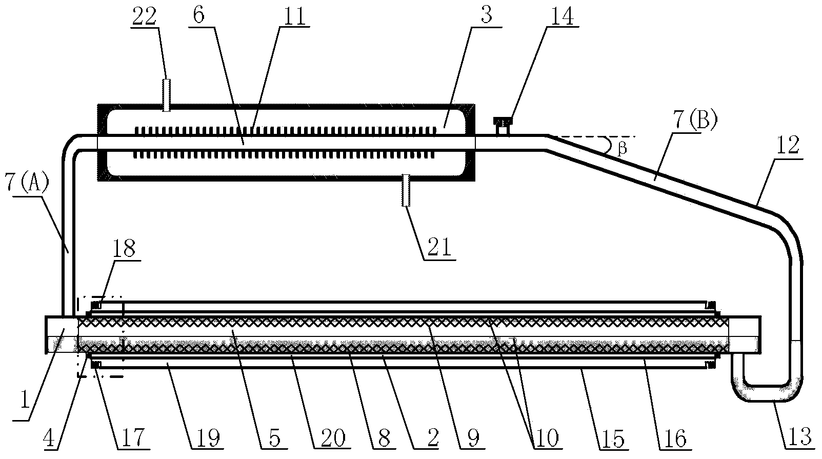
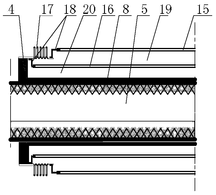
[0032] Such as figure 1 and figure 2As shown, the present invention discloses a solar medium and high temperature loop heat pipe steam generator: it is composed of a loop heat pipe 1, a straight-through all-glass vacuum tube 2, a steam drum 3 and a sealing ring 4; the loop heat pipe 1 is composed of A closed loop composed of evaporating section 5, condensing section 6, first adiabatic section 7(A) and second adiabatic section 7(B); the outer surface of the evaporating section 5 tube is coated with selective absorption coating 8, and the inner wall of the tube is filled with metal Liquid-absorbing core 9, the tube is equipped with heat transfer medium 10; the condensation section 6 is wrapped with metal fins 11; the first adiabatic section 7 (A) is a steam rising pipe, and the second adiabatic section 7 (B) is descended by condensate Pipe 12, U-shaped liquid storage pipe 13 and exhaust valve 14; one end of the first adiabatic section 7 (A) is sealed to the top of one side of ...

Embodiment 2

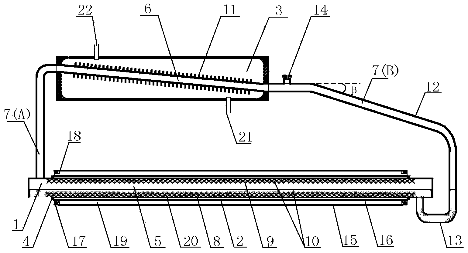
[0035] image 3 Shown is a schematic structural diagram of the solar medium-high temperature loop heat pipe steam generator of this embodiment.

[0036] The structural form and some materials of this embodiment are the same as those of Embodiment 1. The difference is: the material of the loop heat pipe 1 is carbon steel, the diameter of the evaporation section 5 is 100mm, and the length is 4060mm; the length of the condensation section 6 is 3000mm; the height of the center line of the evaporation section 5 and the condensation section 6 is 800mm; the condensate drops The length of the horizontal section of the tube 12 is 100 mm, and the angle β between the inclined section and the horizontal section is 30°; the centerline width of the U-shaped liquid storage tube 13 is 200 mm. The selective absorption coating 8 on the outer surface of the tube in the evaporation section 5 is Ag-Cr 2 o 3 The material has an absorption rate of 96% and an emissivity of 14% under non-vacuum con...

Embodiment 3

[0039] Figure 4 Shown is a schematic structural diagram of the solar medium-high temperature loop heat pipe steam generator of this embodiment. The structural forms, some materials and structural parameters involved in this embodiment are the same as those in Embodiment 1. The difference is that the length of the evaporation section 5 of the loop heat pipe 1 is 2000mm; the diameter of the condensation section 6 is 40mm and the length is 1600mm; The diameter of the condensate downcomer 12 is 40mm; the length of the horizontal section of the condensate downcomer 12 is 70mm, and the angle β between the inclined section and the horizontal section is 10°; the width of the center line of the U-shaped liquid storage pipe 13 is 100mm. The selective absorption coating 8 on the outer surface of the tube in the evaporation section 5 is Ni-SiO 2 The material has an absorption rate of 86% and an emissivity of 4% under non-vacuum conditions; the metal liquid-absorbing core 9 filled in th...


PUM

PropertyMeasurementUnit
Diameteraaaaaaaaaa
Lengthaaaaaaaaaa
Diameteraaaaaaaaaa

Abstract

The invention relates to a solar medium-high-temperature loop heat pipe steam generator which is composed of a loop heat pipe (1), a straight-through all-glass vacuum pipe (2), a steam pocket (3) and a sealing ring (4). The loop heat pipe (1) is a closed loop formed by an evaporation section (5), a condensation section (6), a first heat insulation section (7(A)) and a second heat insulation section (7(B)), the first heat insulation section (7(A)) is a steam ascending pipe, the second heat insulation section (7(B)) is formed by a condensing liquid descending pipe (12) and a U-shaped liquid storage pipe (13), the straight-through all-glass vacuum pipe (2) and the evaporation section (5) are placed coaxially to form an annular non-vacuum space (20), two ends of the annular non-vacuum space (20) are sealed by adopting sealing rings (4), and the steam pocket (3) is in sealed connection with the condensation section (6) of the loop heat pipe (1). The solar medium-high-temperature loop heat pipe steam generator is suitable for groove-type solar DSG technology, high-efficiency phase change of the heat pipe is utilized for heat transfer to heat water in the steam generator so as to directly generate high-temperature steam, system cost is lowered, and system running reliability is improved.

Description

technical field [0001] The invention relates to solar photothermal utilization technology in the field of renewable energy, in particular to a solar medium-high temperature loop heat pipe steam generator, which is mainly used in a trough solar direct steam generation (Direct Steam Generation, DSG) system. Background technique [0002] As a renewable energy source, the development and utilization of solar energy is one of the effective ways to achieve green and sustainable development. The trough solar DSG thermal power generation technology is an economical and effective way to realize the high temperature heat utilization of solar energy, and it is of great significance to solve the problems of fossil resource shortage, environmental pollution and greenhouse effect. The trough DSG system directly uses water / steam as the heat transfer medium, which is environmentally friendly, the heat collection temperature is not limited by the heat transfer medium, and at the same time av...

Claims


Application Information

Patent Timeline
IPC IPC(8): F24J2/24F24J2/05F24J2/32F24J2/46F22B1/00F24S10/40F24S10/70F24S10/95
CPCY02E10/44
Inventor 朱跃钊王银峰陈海军范红途钱裕朱震杨丽
Owner NANJING UNIV OF TECH
Learn More