
Integrated device for group welding, hoisting, machining and assembling of end chassis of rail vehicle

A technology for assembly and welding of rail vehicles, applied in the direction of assembly machines, metal processing equipment, manufacturing tools, etc., can solve problems such as hindering normal progress, troublesome disassembly and assembly, and damage

Active Publication Date: 2015-01-21
CRRC QINGDAO SIFANG CO LTD
View PDF6 Cites 0 Cited by
  • Summary
  • Abstract
  • Description
  • Claims
  • Application Information

AI Technical Summary

Problems solved by technology

The disadvantages are: 1. The error of the reinforcement method of the welding process beam is too large, the manufacturing precision of the parts is not high, and it is easy to produce waste products; 2. According to the structural characteristics, at least five process beams need to be welded in different positions and directions, and there are The setting of the process beam also hinders the normal progress of the process during the machining and assembly process; 3. The process beam is damaged after about 3 cycles of use and needs to be remade, resulting in waste of materials; 4. The process beam is welded Permanent connection method, troublesome disassembly and easy damage to parts

Method used


Image

  • Integrated device for group welding, hoisting, machining and assembling of end chassis of rail vehicle
  • Integrated device for group welding, hoisting, machining and assembling of end chassis of rail vehicle
  • Integrated device for group welding, hoisting, machining and assembling of end chassis of rail vehicle

Examples


Embodiment Construction

[0023] Attached below Figures 2 to 6 The present invention is described in further detail.

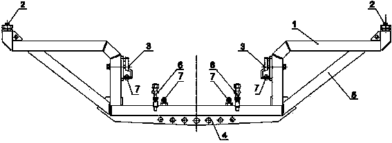
[0024] Such as figure 2 and image 3 As shown, the structure of the integrated device for welding, hoisting, processing and assembling of the rail vehicle end chassis of the present invention is as follows.

[0025] The main body frame 1 has a cross-sectional shape of U-shape and double-L-shape docking, the ends of each L-shaped long side are respectively docked with one end of the U-shaped mouth, and the direction of the short side of the L-shape is consistent with the direction of the U-shaped opening.

[0026] The main body frame 1 is provided with several fastening mechanisms and spacing adjustment mechanisms at the side walls of the opposite pillars in the U-shaped groove, and is respectively provided with fastening mechanisms at the ends of the short sides of the L-shaped groove; There is a hoisting beam matched with the crane; there is a supporting beam connecting the outer...


PUM


Abstract

The invention provides an integrated device for group welding, hoisting, machining and assembling of an end chassis of a rail vehicle. The integrated device comprises a body frame, wherein according to the cross-section shape, the body frame is formed by connecting a U-shaped body with double L-shaped bodies in a butt joint mode. The end of the long side of each L-shape body is connected with one end of a U-shaped opening in a butt joint mode, and the direction of the short side of each L-shaped body is the same as the direction of the U-shaped opening. The inner bottom of a U-shaped groove of the body frame is provided with two bottom fastening mechanisms and two distance adjusting mechanisms, the two side walls of the U-shaped groove of the body frame are each provided with a side direction fastening mechanism and a distance adjusting mechanism, and the end of the short side of each L-shaped body of the body frame is provided with an end fastening mechanism. The outer wall of the bottom of the U-shaped groove is provided with hoisting beams matched with a hoist. Supporting beams are arranged between the outer wall of the U-shaped groove and the long walls of the L-shaped bodies and used for connecting the outer wall of the U-shaped groove with the long walls of the L-shaped bodies. The integrated device has the advantages of being simple in structure, low in cost, capable of preventing the end chassis from deforming and applicable to the production links of welding, hoisting, machining and assembling, lowering the manufacturing cost, and improving the production efficiency.

Description

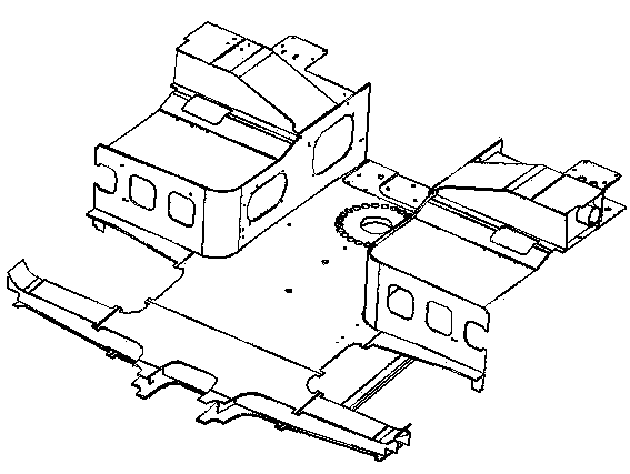
technical field [0001] The invention relates to a process equipment, in particular to an integrated device for welding, hoisting, processing and assembling an end chassis of a low-floor rail vehicle. [0002] Background technique [0003] The end underframe of a low-floor rail vehicle is the key structure for docking with the bogie. In the manufacturing process of the rail vehicle body, the end underframe needs to be assembled and welded to the plate before machining, and then turned over and transferred to the car body for assembly. In tooling, the chassis is finally assembled with other parts of the car body. [0004] Since the chassis at the end of the car body has the unique structural characteristics of a large-section thin plate box, such as figure 1 As shown, its length and width are more than two meters, and its shape is complex and extremely irregular, so there will be great errors in the assembly and welding process. After being welded into one body, it needs to...

Claims


Application Information

Patent Timeline
Patent Type & Authority Applications(China)
IPC IPC(8): B23P21/00
CPCB23P21/00
Inventor 赵延强梁文建万帅刘永刚何智勇
Owner CRRC QINGDAO SIFANG CO LTD
Learn More