Overflow type iron bath slag melting pool and slag removal method thereof

An overflow type and slag technology, which is applied in the petroleum industry, the manufacture of combustible gas, and the mechanical details of gasification devices, etc., can solve the problems of poor fluidity of liquid slag, blockage of slag discharge port, and insufficient temperature, so as to improve operating efficiency and Operational safety, solving poor slag discharge, and ensuring smooth slag discharge

Active Publication Date: 2015-01-21
CCTEG CHINA COAL RES INST
View PDF2 Cites 6 Cited by
  • Summary
  • Abstract
  • Description
  • Claims
  • Application Information

AI Technical Summary

Problems solved by technology

For coal with high ash melting point, because the temperature in the slag pool is not high enough, the fluidity of liquid slag is poor, resulting in blockage of the slag outlet, affecting the normal operation of the slag gasifier
In addition, the arrangement of annular burners at the bottom of the slag outlet has problems such as complicated connection, large natural gas consumption, and difficulty in controlling the combustion flame of the annular burners.

Method used


Image

  • Overflow type iron bath slag melting pool and slag removal method thereof
  • Overflow type iron bath slag melting pool and slag removal method thereof

Examples


Embodiment 1

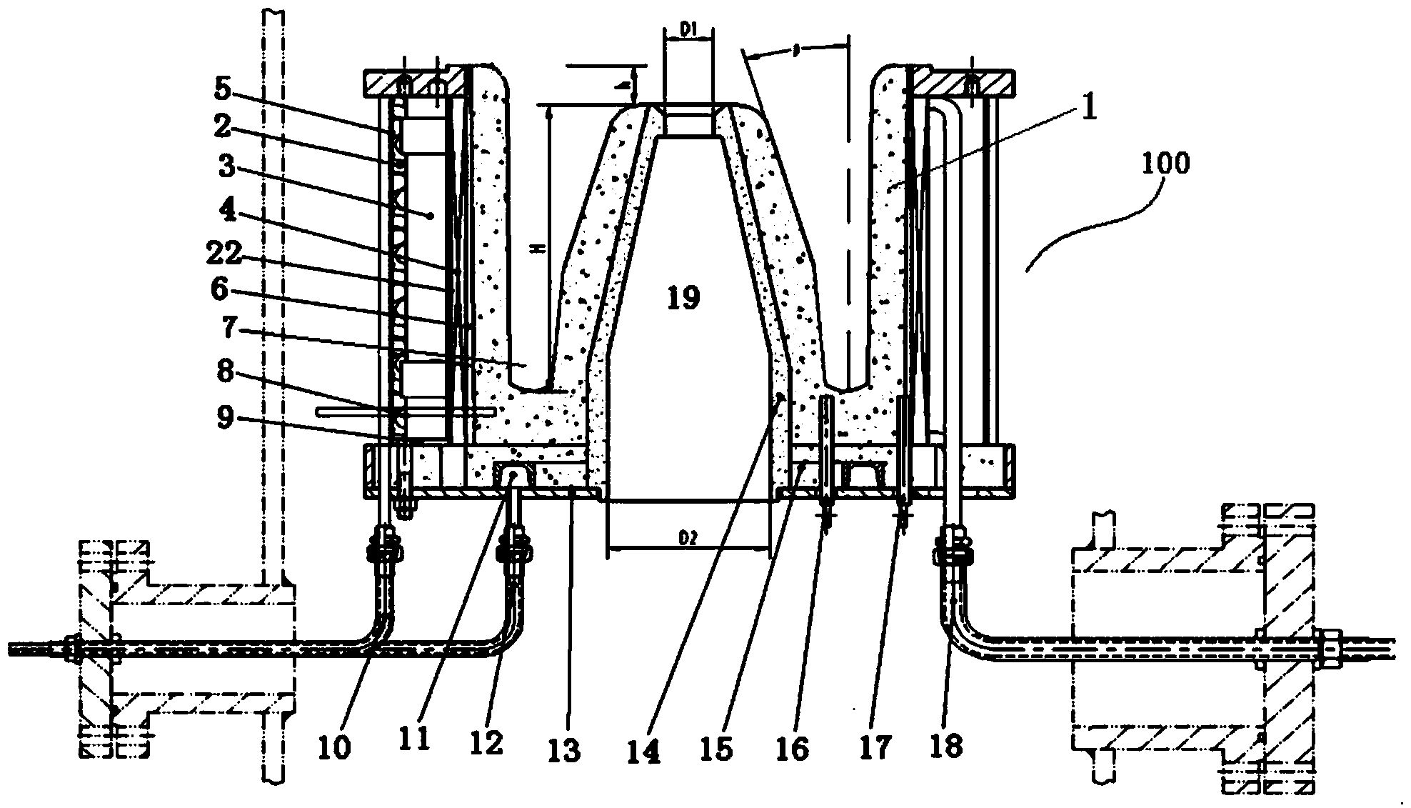
[0024] Such as figure 1 As shown, this embodiment provides an overflow iron bath slag pool 100 with an inner diameter of 3.0 m or less. The slag pool 100 is installed under the furnace body of the slag gasifier, which includes an inverted "M" section Shaped annular furnace lining 1, the middle part of the furnace lining 1 has a hollow conical slag outlet 19, the overflow port at the upper end of the slag outlet 19 is slightly lower than the upper edge of the outer wall of the furnace lining 1 in the height direction, the outer wall of the furnace lining 1 and the slag outlet Form an annular slag pond 7 between 19. An inductor 4 is installed outside the furnace lining 1 for inductively heating the metal iron in the slag pool 7 . A magnetic yoke 3 is installed outside the inductor 4 for shielding the magnetic field generated by the inductor 4 and preventing the external metal components and instruments of the slag pool 100 from being affected by the magnetic field. A water-coo...

Embodiment 2

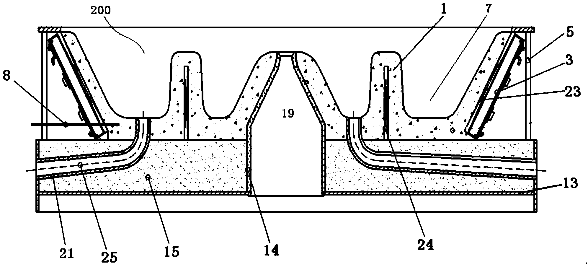
[0036] Such as figure 2 As shown, this implementation provides an overflow iron bath slag pool 200 with an inner diameter of 3.0 m or more. The slag pool 200 is also installed under the furnace body of the slag gasifier, which includes a "W" shaped section The ring-shaped furnace lining 1, the middle part of the furnace lining 1 has a hollow conical slagging outlet 19, the overflow opening at the upper end of the slagging outlet 19 is slightly lower than the upper edge of the outer wall of the furnace lining 1 in the height direction, and the outer wall of the furnace lining 1 is connected to the slagging outlet 19 An annular slag pool 7 is formed between them. Due to the limitation of the electromagnetic induction distance, an integrated annular boss is arranged on the furnace lining 1 inside the slag pool 7. An inner inductor 24 is installed inside the annular boss, and an outer inductor 23 is installed outside the furnace lining 1 to sense Both the device 24 and the induc...

Embodiment 1

[0047] The inner diameter of the overflow iron bath slag pool used in the test is 2.0m, the diameter of the overflow at the upper end of the slag pool is 100mm, and the diameter of the open part at the lower end is 600mm. The angle between the side wall of the slag outlet and the axis of the slag pool is 30°. The depth of the slag pool is 800mm, and the overflow at the upper end of the slag pool is 120mm lower than the outer edge of the slag pool.

[0048] The side wall of the slag outlet is a prefabricated orifice, and the chemical composition of the prefabricated orifice is w(Al 2 o 3 )90%, w(Fe 2 o 3 ) 1.3%, apparent porosity 20%, load softening temperature 1700°C, refractoriness 1790°C, normal temperature compressive strength 65MPa, bulk density 3.2g / cm 3 , specifically brown corundum.

[0049] A layer of furnace lining is poured on the working surface of the slag pool, the thickness of the furnace lining is 80mm, and the chemical composition of the furnace lining is ...


PUM

PropertyMeasurementUnit
strengthaaaaaaaaaa
thicknessaaaaaaaaaa
compressive strengthaaaaaaaaaa

Abstract

The invention relates to an overflow type iron bath slag melting pool and a slag removal method thereof. The overflow type iron bath slag melting pool is characterized by comprising an annular furnace lining, wherein a hollow slag opening with the shape of cone frustum is formed in the middle of the furnace lining; an overflow port in the upper end of the slag opening is slightly lower than the upper edge of the outer wall of the furnace lining in the height direction; an annular slag pool is formed between the outer wall of the furnace lining and the slag opening; an inductor is arranged on the outer part of the furnace lining; a magnet yoke is arranged on the outer part of the inductor; a water cooled jacket is arranged on the outer part of the magnet yoke; an annular tray shaped furnace bottom is arranged below the furnace lining; a through hole which corresponds to the slag opening is formed in the middle of the furnace bottom; and a furnace charge layer is arranged between the furnace bottom and the furnace lining. With the adoption of an electromagnetic induction heating and melting principle, metal iron is added into the bottom of the slag pool in advance and is molten into molten iron through induction heating so as to continuously supply heat to liquid slag in the slag pool, and the liquid slag can preserve the flowing temperature to flow out of the overflow port of the slag pool. The slag is removed by adopting an overflow mode, a phenomenon that the slag removal is unsmooth due to small slag opening is avoided, and the operating efficiency and operating safety of a fixed bed slag gasifier are improved.

Description

technical field [0001] The invention relates to a slag pool and a slag discharge method, in particular to an overflow iron bath slag pool and a slag discharge method. Background technique [0002] At present, the slagging device at the lower part of the traditional slag gasifier body is mainly an inverted conical slag pool. The inner surface of the slag pool is in a convergent configuration from the upper end of the slag pool to the lower end of the slag pool. The horizontal slope of the inner surface of the slag pool is 25°~60°. At the same time, the slag discharger adopts the intermittent slag discharge method, that is, a pressure difference detection is installed between the furnace body and the quenching chamber, and it is interlocked with the release valve of the quenching chamber. When the liquid slag in the molten state accumulates to a certain height in the slag pool, there will be an exact pressure difference value, which triggers the interlock, and the release val...

Claims


Application Information

Patent Timeline
Patent Type & Authority Applications(China)
IPC IPC(8): C10J3/72C10J3/34
CPCC10J3/34C10J3/72C10J2200/09
Inventor 董卫果张科达陈贵锋王鹏晁俊楠徐春霞文芳杨宗仁唐楠郭良元李小亮张庆伟
Owner CCTEG CHINA COAL RES INST
Why Eureka
Try Eureka