Joint section structure for hybrid beam cable-stayed bridge and construction method thereof

A combination of section and structure technology, applied in the direction of cable-stayed bridges, bridges, bridge parts, etc., can solve the problems of inconvenient construction, poor combination effect, complex structure, etc., and achieve the effect of convenient adjustment, good use effect and simple structure

Inactive Publication Date: 2015-01-21
TONGJI UNIV
View PDF5 Cites 21 Cited by
  • Summary
  • Abstract
  • Description
  • Claims
  • Application Information

AI Technical Summary

Problems solved by technology

[0004] The technical problem to be solved by the present invention is to provide a combination section structure and construction method for a hybrid girder cable-stayed bridge in view of the deficiencies in the above-mentioned prior art, which has a simple structure, reasonable design, fast construction speed, and easy construction quality assurance. It can effectively solve the problems of complex structure, inconvenient construction and poor bonding effect in the steel-concrete joint structure.

Method used


Image

  • Joint section structure for hybrid beam cable-stayed bridge and construction method thereof
  • Joint section structure for hybrid beam cable-stayed bridge and construction method thereof
  • Joint section structure for hybrid beam cable-stayed bridge and construction method thereof

Examples


Embodiment Construction

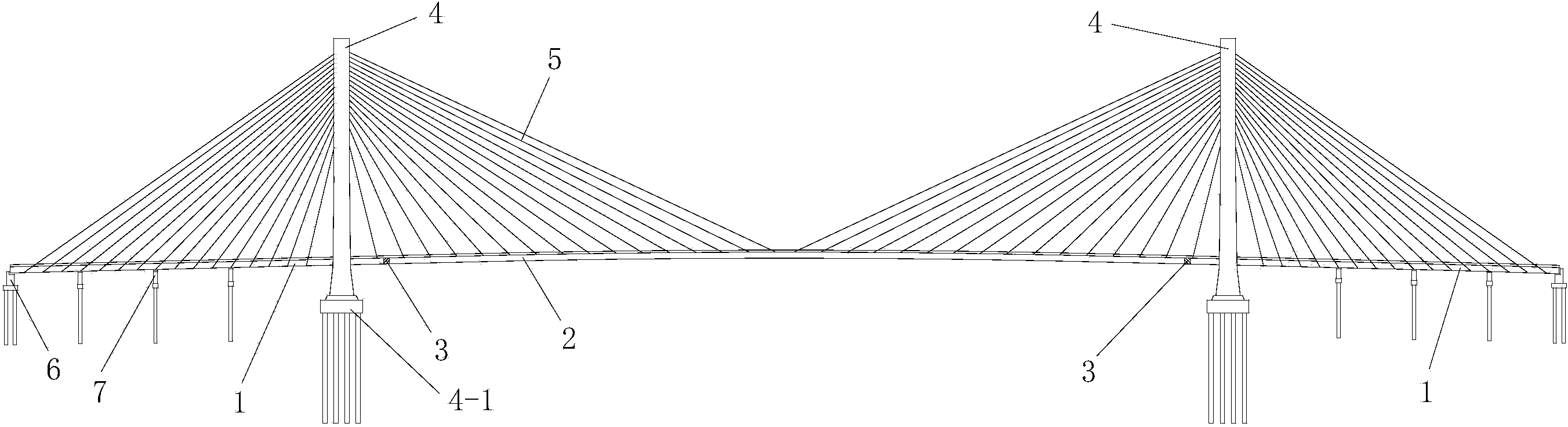
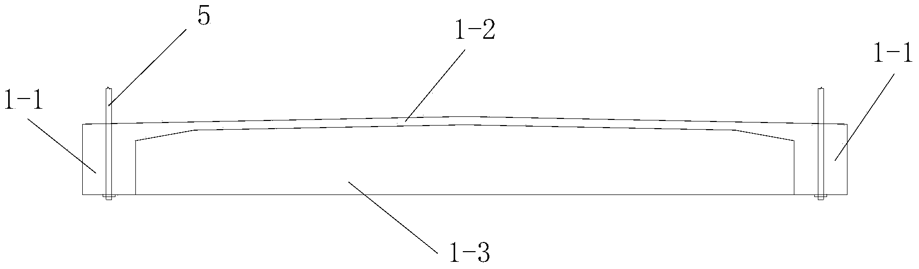
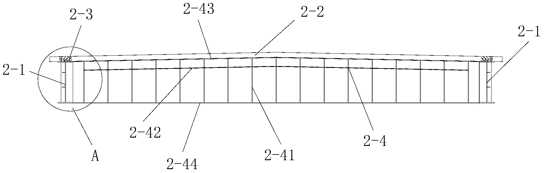
[0058] Such as Figure 4 The composite girder cable-stayed bridge shown is constructed with a combined section, including a concrete beam-composite beam connection structure connected between a concrete beam 1 and a composite beam 2, and the composite beam 2 includes steel main beams arranged along the longitudinal direction Beam 2-1, see image 3 and Figure 3-1 . The cross-sectional shape of the steel girder 2-1 is I-shaped and it includes a steel girder top plate 2-11, a steel girder bottom plate 2-12 below the steel girder top plate 2-11 and a steel girder top plate connected to the steel girder top plate. The main beam steel web 2-13 between 2-11 and the steel main beam bottom plate 2-12, the steel main beam top plate 2-11, the steel main beam bottom plate 2-12 and the main beam steel web 2-13 are all Arranged along the longitudinal bridge. combine Figure 5 , Figure 6 , Figure 7 and Figure 8 , the steel main beam top plate 2-11 and the steel main beam bottom p...


PUM


Abstract

The invention discloses a joint section structure for a hybrid beam cable-stayed bridge. The joint section structure comprises a concrete beam-combined beam connecting structure connected between a concrete beam and a combined beam, wherein the combined beam comprises steel girders distributed in the longitudinal direction of the bridge, the steel girders are I-shaped and comprise steel girder top plates, steel girder base plates and steel girder web plates. The steel girder top plates and the steel girder base plates extend into the concrete beam, and the concrete beam-combined beam connecting structure comprises a front pressure bearing plate, a rear pressure bearing plate and a joint section steel web plate. The joint section structure is simple, reasonable in design, high in construction speed and good in using effect, and the problems of complicated structure, poor joint effect and the like existing in a steel-concrete joint portion structure can be solved. The invention further discloses a construction method of the joint section structure. The construction method comprises the steps of 1 erecting a construction support; 2 hoisting a steel structure; 3 constructing the concrete beam-combined beam connecting structure; 4 casting concrete. The construction method is simple in step, reasonable in design, convenient to construct, high in construction speed and good in construction effect.

Description

technical field [0001] The invention belongs to the technical field of bridge construction, and in particular relates to a joint section structure for a mixed girder cable-stayed bridge and a construction method thereof. Background technique [0002] The main girder materials of cable-stayed bridges generally include steel and concrete. The main girders can be divided into steel girders, concrete girders, composite girders and hybrid girders according to the different combinations of these two materials. Composite beams are composed of steel and concrete in the cross section, which is a combination of different materials in the cross section. The advantages of composite beams are that concrete slabs are used instead of orthotropic steel bridge decks, which are economical, have high rigidity, and can be disassembled into small components for easy transportation and installation. However, the disadvantage is that the bridge deck cracking problem needs to be solved. The compos...

Claims


Application Information

Patent Timeline
Patent Type & Authority Applications(China)
IPC IPC(8): E01D11/04E01D2/00E01D19/00E01D19/12E01D21/00
CPCE01D2/00E01D11/04E01D19/00E01D19/125E01D21/00E01D2101/285
Inventor 蒲广宁肖汝诚张晓栋程进
Owner TONGJI UNIV
Why Eureka
Try Eureka