Engine system and control method thereof
An engine system and engine technology, which is applied in the direction of engine components, machines/engines, mechanical equipment, etc., can solve the problem that the emission of nitrogen oxides in exhaust gas cannot be effectively reduced, urea and exhaust gas cannot be fully mixed, and exhaust gas cannot be well eliminated. problems, to achieve the effect of saving costs, avoiding secondary pollution, and improving utilization
- Summary
- Abstract
- Description
- Claims
- Application Information
AI Technical Summary
Problems solved by technology
Method used
Image

Examples
Embodiment approach 1
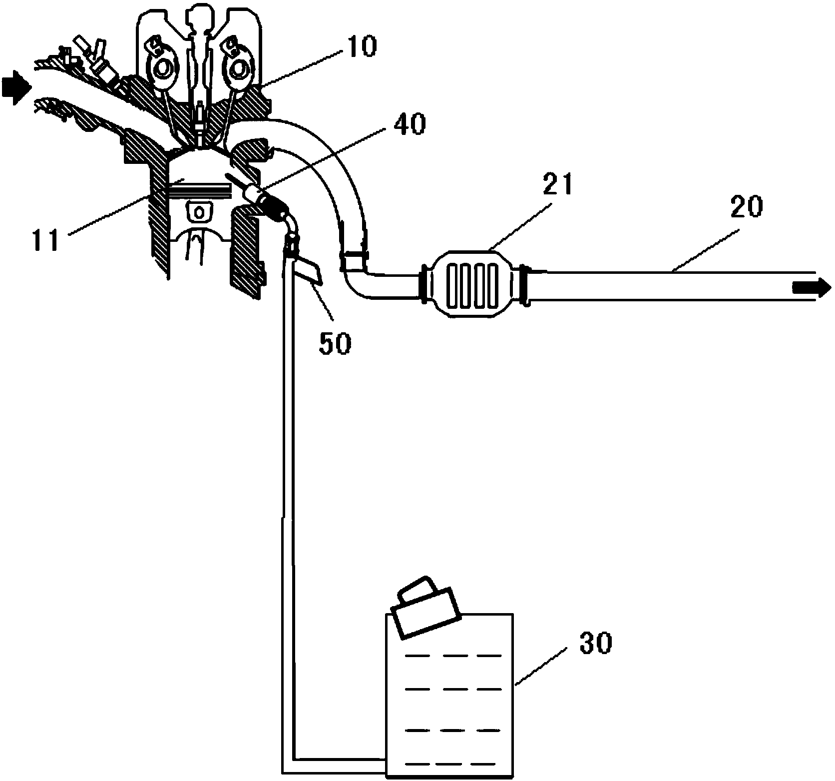
[0045] Below, refer to figure 1 An engine system according to Embodiment 1 of the present invention will be described.
[0046] Such as figure 1 As shown, the engine system includes: an engine 10 having a cylinder 11 , and an exhaust pipe 20 that discharges exhaust gas generated in the cylinder 11 of the engine 10 . Here, a purifier 21 for catalytically treating harmful substances in exhaust gas is connected in the middle of the exhaust pipe 20 , but this purifier 21 is not essential.
[0047] In addition, the engine system further includes: a urea storage tank 30 storing urea; and a nozzle 40 communicating with the urea storage tank 30 via an injection control valve 50 to inject urea into the cylinder 11 .
[0048] In addition, the engine system may also include a control unit (such as an ECU control unit) to control the opening and closing of the injection control valve 50 according to the operating conditions of the engine 10 (such as load and speed, etc.), so as to use t...
Embodiment approach 2
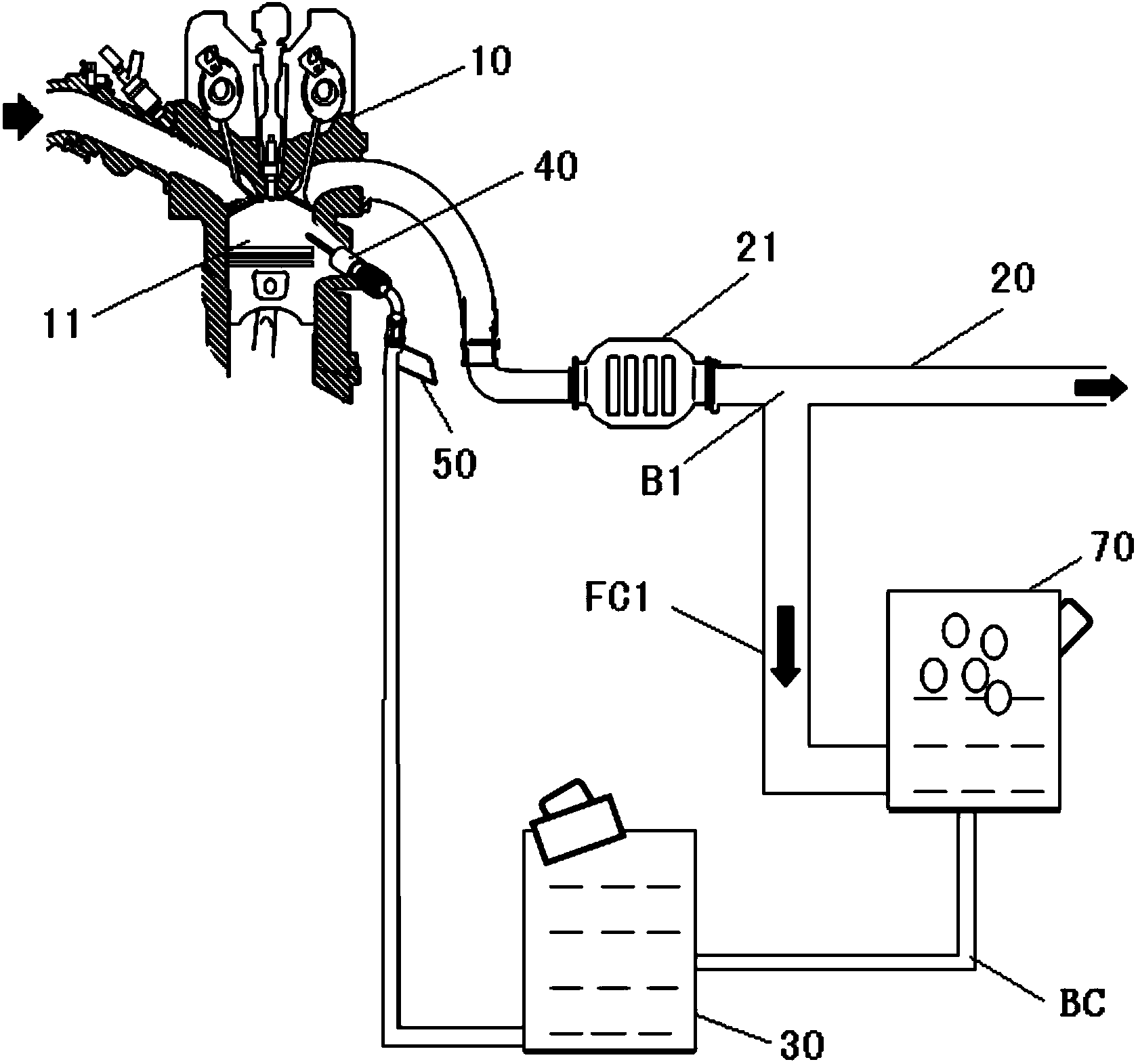
[0057] Below, refer to image 3 An engine system according to Embodiment 2 of the present invention will be described. Here, the same reference numerals are assigned to the same parts as those in Embodiment 1 above, and detailed description thereof will be omitted.
[0058] In this embodiment, if image 3 As shown, the engine system includes the engine 10, the exhaust pipe 20, the urea storage tank 30, the injection nozzle 40, the injection control valve 50 and the unshown control unit as in the first embodiment, and also includes a first branch pipe FC1, the urea recovery tank 70 and the urea replenishment pipe BC, wherein the first branch pipe FC1 branches out from the first branch part B1 of the exhaust pipe 20, and communicates with the urea recovery tank 70, and the urea recovery tank 70 is connected to the The urea in the exhaust gas delivered by the first branch portion B1 of the exhaust pipe 20 is recovered, and the urea replenishment pipe BC connects the urea recove...
Embodiment approach 3
[0067] Below, refer to Figure 5 An engine system according to Embodiment 3 of the present invention will be described. Here, the same reference numerals are assigned to the same parts as those of Embodiments 1 and 2 and their modifications described above, and detailed description thereof will be omitted.
[0068] In this embodiment, if Figure 5 As shown, the engine system includes an engine 10, an exhaust pipe 20, a urea storage tank 30, a nozzle 40, an injection control valve 50, an unillustrated control unit, and a first branch pipe FC1 in addition to the above-mentioned modified example of the second embodiment. , urea recovery tank 70, urea replenishment pipe BC, filter 80 and urea recovery pump 90, also includes a second branch pipe FC2, a waste gas intercepting valve V1 and a waste gas release valve V2, wherein the second branch pipe FC2 from The second branch part B2 of the exhaust pipe 20 on the downstream side of the exhaust gas discharge direction than the first...
PUM
 Abstract
Description
Claims
Application Information
 - R&D
- Intellectual Property
- Life Sciences
- Materials
- Tech Scout
- Unparalleled Data Quality
- Higher Quality Content
- 60% Fewer Hallucinations
Browse by: Latest US Patents, China's latest patents, Technical Efficacy Thesaurus, Application Domain, Technology Topic, Popular Technical Reports.
© 2025 PatSnap. All rights reserved.Legal|Privacy policy|Modern Slavery Act Transparency Statement|Sitemap|About US| Contact US: help@patsnap.com