Monitoring system for electric vehicle charging and converting station

A charging and swapping station and monitoring system technology, applied in the field of electric vehicle charging and swapping station monitoring systems, can solve the problems of inability to monitor and operate equipment in the entire station, increased workload of engineering personnel, and large number of configurations, and achieve fast access to charging equipment. , the effect of reducing communication connection management and improving reliability

Active Publication Date: 2015-01-21
STATE GRID CORP OF CHINA +5
View PDF5 Cites 15 Cited by
  • Summary
  • Abstract
  • Description
  • Claims
  • Application Information

AI Technical Summary

Problems solved by technology

Each different sub-box charger has different communication configuration information. In the face of thousands of charging equipment, if these electrical quantities are implemented in the form of traditional measurement points, there will be configuration quantities in the specific project implementation process. Large, error-prone, difficult to manage, etc. If the configuration information of the charger is changed, the workload of the engineering staff will be doubled and disastrous
In addition, the monitoring background is the center of the entire equipment monitoring. If there is a temporary failure in the monitoring background, it will face the situation that the entire station equipment cannot be monitored and operated.

Method used


Image

  • Monitoring system for electric vehicle charging and converting station
  • Monitoring system for electric vehicle charging and converting station
  • Monitoring system for electric vehicle charging and converting station

Examples


Embodiment Construction

[0021] The present invention will be further introduced below in conjunction with the accompanying drawings and specific embodiments.

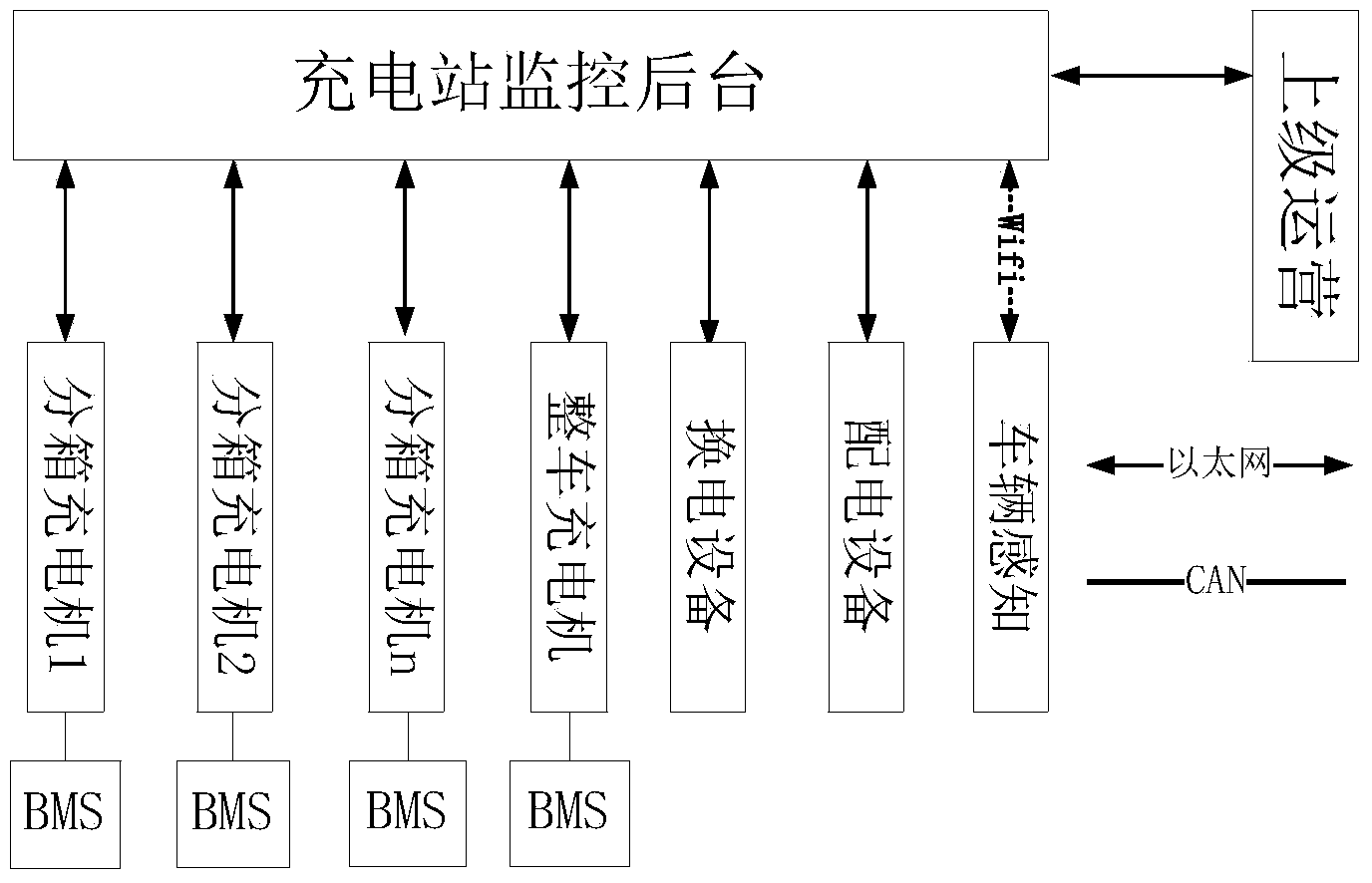
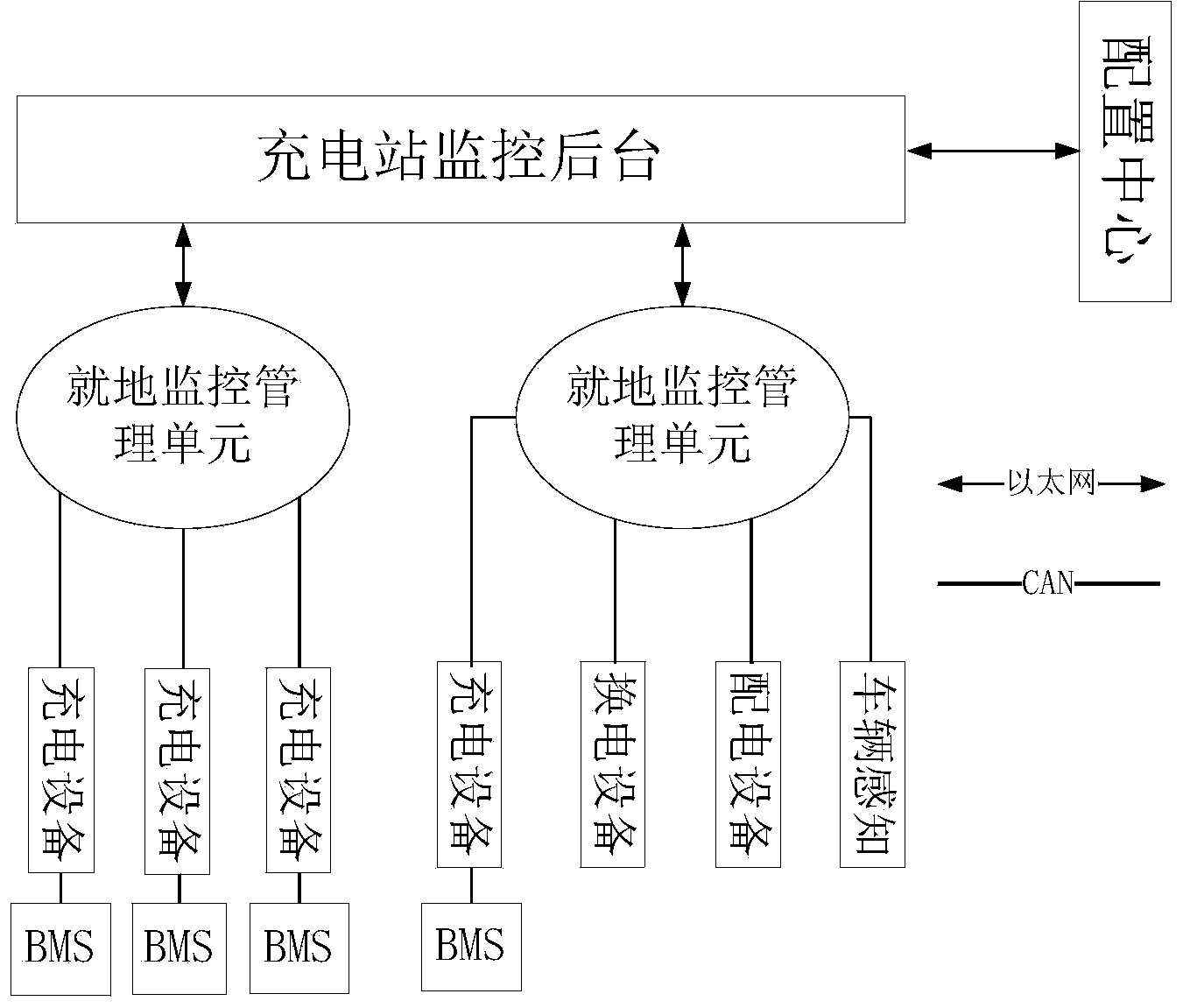
[0022] Such as Figure 2 ~ Figure 3 Shown is a structural diagram of an embodiment of the monitoring system for electric vehicle charging and swapping stations of the present invention. The entire system is divided into three layers, the background monitoring layer, the on-site monitoring management unit and the charging and swapping equipment layer. Each monitoring device of the whole station is connected to the on-site monitoring intelligent terminal through the Can port or serial port, and the on-site monitoring intelligent terminal is connected to the monitoring background through Ethernet. The communication protocol adopts the IEC104 message header, and the ASDU entity part of the message is sent in the form of a service package of the charging and swapping station.

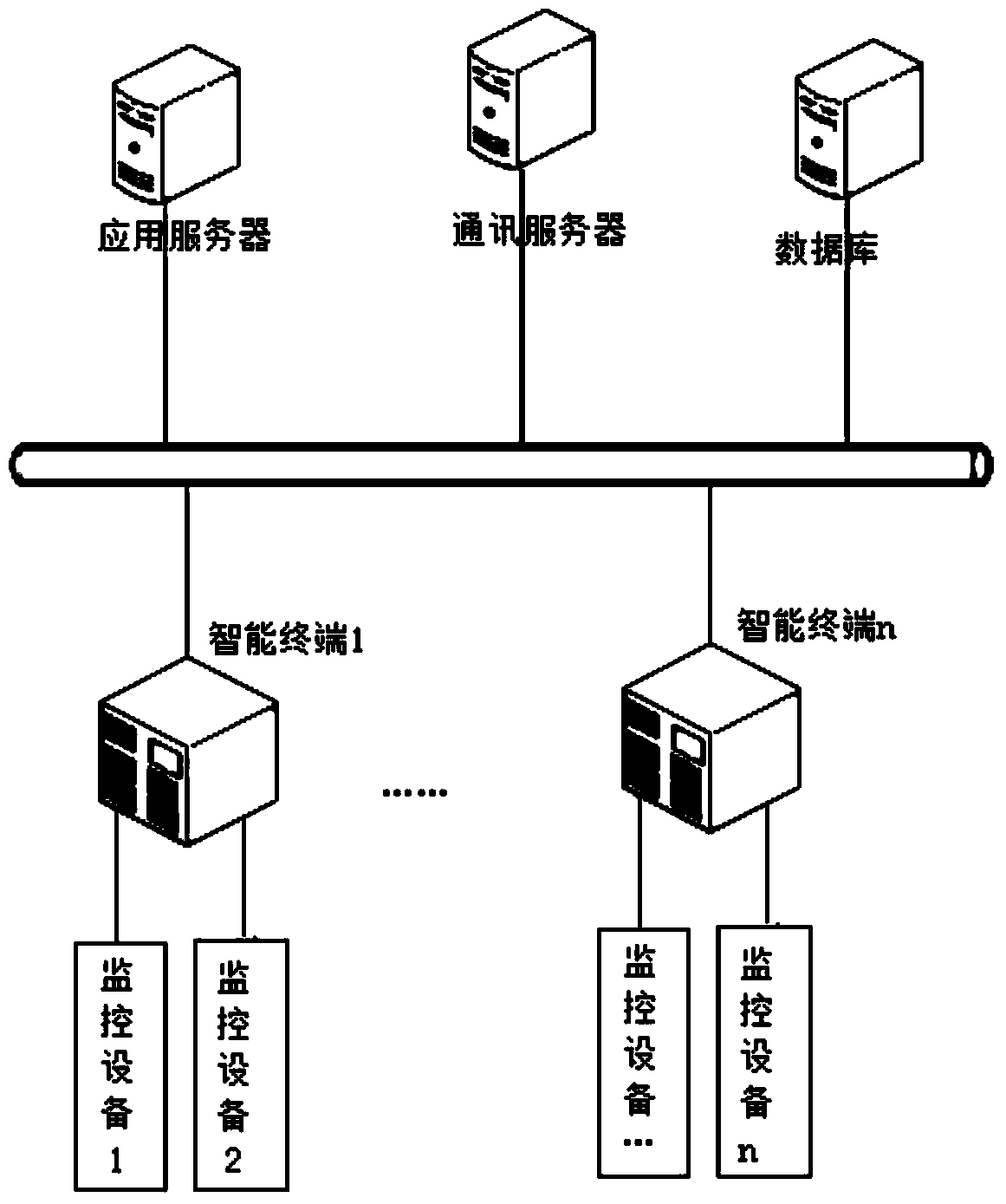
[0023] The background monitoring layer is composed of servers, worksta...


PUM


Abstract

The invention discloses a monitoring system for an electric vehicle charging and converting station. The monitoring system comprises a background monitoring layer, an in-situ monitoring management unit and a charging and converting device layer. An in-situ monitoring intelligent terminal is connected with a monitoring background through the Ethernet, data information of monitoring devices corresponding to charging devices are integrated and uploaded to the monitoring background, and the in-situ monitoring management unit is responsible for completing information integration of the charging devices and data interaction between the charging devices and the monitoring background. According to the monitoring system for the electric vehicle charging and converting station, the in-situ monitoring management unit is adopted to be responsible for and manage data exchange between the monitoring devices of the charging devices and converting devices and the monitoring background, and information exchange is conducted with the monitoring background according to the packed data transferring rule. Due to the fact that the monitoring devices share one in-situ monitoring management unit, the communication connection management between the monitoring background and the monitoring devices is greatly reduced, the reliability of the monitoring system is improved, and the number of the monitoring devices is increased.

Description

technical field [0001] The invention belongs to the technical field of computer network communication, and in particular relates to a monitoring system for an electric vehicle charging and replacing station. Background technique [0002] The charging and swapping station monitoring system is a "layered distributed" network structure, and its backbone network is Ethernet, which is interconnected through CAN bus, serial bus, wireless network (WIFI), RFID radio frequency identification and other communication networks distributed in different work sites. Construct. [0003] The overall network structure of the existing charging and swapping station monitoring system is as follows: figure 1 shown, from figure 1 It can be seen that the monitoring equipment of the charging and swapping station monitoring system generally includes sub-box chargers, vehicle chargers, battery swapping equipment, power distribution equipment, and vehicle sensing equipment, etc., and each device is i...

Claims


Application Information

Patent Timeline
IPC IPC(8): H02J7/00
CPCB60L53/60Y02T10/70Y02T10/7072Y02T90/12
Inventor 徐怡山连湛伟克潇邓建慎张艳芳王艳徐鹏李洪峰李国杰陈志刚
Owner STATE GRID CORP OF CHINA
Why Eureka
Try Eureka