Heat radiator module special for concentrating photovoltaic solar heater

A concentrating photovoltaic and radiator technology, applied in the field of solar power generation, can solve the problems of increasing product cost, increasing the cost of connecting wires and external power supply, increasing production workload, etc., and achieves processing efficiency, low production cost, and improved heat dissipation. effect of effect

Inactive Publication Date: 2015-01-21
成都聚合科技有限公司
View PDF4 Cites 19 Cited by
  • Summary
  • Abstract
  • Description
  • Claims
  • Application Information

AI Technical Summary

Problems solved by technology

Since the light energy gathered through the lens is very strong, the working temperature on the surface of the concentrating photovoltaic photoelectric conversion receiver is very high. In order to ensure that the concentrating photovoltaic photoelectric conversion receiver can work stably within the normal temperature range, generally The photovoltaic photoelectric conversion receiver is directly bonded to the radiator, and the cooling fins at the lower end of the radiator are directly exposed to the outside air, and the heat generated by the concentrated sunlight is directly dissipated by the radiator to the outside air. The distribution of power and heat energy is done by adding a fan on the radiator. In this way, in addition to increasing the cost of the fan, it will also increase the cost of the connecting wire and external power supply, as well as increase the workload of production. Installing a radiator will lead to an increase in product cost; at the same time, for the dissipation of heat with increasing power, the area of ​​the radiator must be increased, which greatly increases the weight and cost of the radiator

Method used


Image

  • Heat radiator module special for concentrating photovoltaic solar heater
  • Heat radiator module special for concentrating photovoltaic solar heater
  • Heat radiator module special for concentrating photovoltaic solar heater

Examples


Embodiment Construction

[0018] The present invention will be further described below in conjunction with the accompanying drawings.

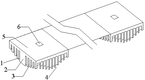
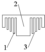
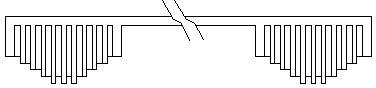
[0019] A special radiator module for concentrated photovoltaic solar energy, such as Figure 1~6 As shown, it includes secondary cooling fins 1 , main cooling fins 2 , radiator bottom plate 5 , and installation area 6 for concentrating photovoltaic photoelectric conversion receivers. The secondary cooling fins 1 are composed of multiple rows of cylindrical arrays or multiple rows of elliptical cylindrical arrays and a graphic array formed by splicing the surrounding arrays into squares and semicircles. The secondary cooling fins 1 start from the center of the main cooling fins. 2 Arranged in descending order according to the height, the inner and surrounding arrays of the secondary heat dissipation fins 1 are staggered in pairs, the main heat dissipation fins 2 are arranged in a row of rectangular column arrays, and the main heat dissipation fins 2 are two Above, ther...


PUM


Abstract

The invention relates to a heat radiator module special for a concentrating photovoltaic solar heater, and belongs to the technical field of solar power generation. The heat radiator module comprises primary cooling fins, secondary cooling fins, heat radiator base plates and concentrating photovoltaic photoelectric conversion receiver mounting areas. A primary cooling fin array and secondary cooling fin arrays in two different shapes are arranged on one side of each heat radiator base plate, the secondary cooling fins are arranged in a progressively decreasing mode from the primary cooling fins in the centers to the peripheries according to the height, and the concentrating photovoltaic photoelectric conversion receiver mounting areas are arranged on the other sides of the heat radiator base plates. A heat radiator is simple in structure and low in manufacturing cost. The cooling fins of the heat radiator are arranged in an array mode, the weight is reduced, that is, the secondary cooling fins are lower than the primary cooling fins, and therefore it can be guaranteed that heat on the primary cooling fins is transferred into air fast, and the heat radiation effect of the heat radiator is greatly improved. Multiple heat radiators can be mounted at a time, and processing efficiency is improved greatly.

Description

technical field [0001] The invention relates to a photovoltaic heat dissipation component, in particular to a radiator module dedicated to concentrating photovoltaic solar energy, which belongs to the technical field of solar power generation. Background technique [0002] The concentrated photovoltaic photoelectric conversion receiver is the core component of the concentrated photovoltaic power generation system, which is used to directly convert the light energy gathered by the lens into electrical energy. Since the light energy gathered through the lens is very strong, the working temperature on the surface of the concentrating photovoltaic photoelectric conversion receiver is very high. In order to ensure that the concentrating photovoltaic photoelectric conversion receiver can work stably within the normal temperature range, generally The photovoltaic photoelectric conversion receiver is directly bonded to the radiator, and the cooling fins at the lower end of t...

Claims


Application Information

Patent Timeline
Patent Type & Authority Applications(China)
IPC IPC(8): H02S40/42
CPCH02S40/00Y02E10/50
Inventor 王永向
Owner 成都聚合科技有限公司
Why Eureka
Try Eureka