Oil-water separation tank

A technology of oil-water separation tank and oil tank, which is applied in liquid separation, separation method, liquid separation through thermal diffusion, etc., can solve the problems that oil-water cannot be separated, shorten the time of oil-water separation, etc., achieve simple and effective liquid temperature, reduce production cost, The effect of raising the temperature of the liquid

Inactive Publication Date: 2015-01-28
QINGDAO KANGHEWEIYE COMML
View PDF5 Cites 4 Cited by
  • Summary
  • Abstract
  • Description
  • Claims
  • Application Information

AI Technical Summary

Problems solved by technology

[0003] The present invention mainly aims at the above problems, and provides a simple and effective method for increasing the temperature of the liquid, changing the density difference between the oil and water, so that the oil and water can be separated quickly, thereby shortening the oil and water separation time, and achieving a better separation effect. The most important thing is to solve the problem that oil and water cannot be separated in winter, improve production efficiency and reduce the loss of raw material oil, thereby reducing the production cost of the separation tank. The technical scheme is as follows:

Method used


Image

  • Oil-water separation tank

Examples


Embodiment Construction

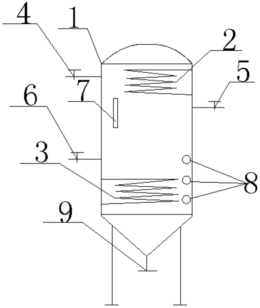
[0011] Below in conjunction with accompanying drawing and example the present invention will be further described:

[0012] Such as figure 1 As shown, the oil-water separation tank includes: an oil tank 1, a condensation coil 2, a heating coil 3, a vent valve 4, a feed port 5, a discharge port 6, a sight glass 7 and a water cut port 8, and the oil tank is divided into 1 It is divided into three parts: heating zone, condensation zone and observation zone. The oil tank 1 is divided into inner and outer layers, and the inner layer is a sealed space when the vent valve 4, the feed port 5, the discharge port 6 and the water cut port 9 are closed. The condensing coil 2 is wound in the outer chamber at the top of the oil tank 1 to form a condensation zone, and the heating coil 3 is coiled in the outer chamber at the bottom of the oil tank 1 to form a heating area. The upper right half of the oil tank 1 is provided with There is a feed port 5, the lower half of the left side of the o...


PUM


Abstract

The invention provides an oil-water separation tank. The oil-water separation tank comprises an oil tank, a condensation coiled pipe, a heating coiled pipe, an emptying valve, a feeding hole, a discharging hole, sight glass and a water shearing opening, wherein the oil tank is divided into three parts, namely a heating region, a condensation region and an observation region; the oil tank is divided into inner and outer layers; the inner layer is a sealed space when the emptying valve, the feeding hole, the discharging hole and the water shearing opening are closed; the condensation coiled pipe is wound in an outer layer cavity at the top end of the oil tank to form a condensation region; the heating coiled pipe is wound in an outer layer cavity at the bottom end of the oil tank to form a heating region; the feeding hole is formed in the upper half part of the right side of the oil tank and the discharging hole is formed in the lower half part of the left side of the oil tank; the water shearing opening is formed in the bottom end of the oil tank; the emptying valve is mounted at the upper half part of the left side of the oil tank; and the surface of the tank wall of the condensation region is coated by a smooth coating so that oil drops can slide off. According to the oil-water separation tank, a simple and efficient method for improving the temperature of liquid is adopted and the density difference of an oil phase and a water phase is changed so that the oil and the water can be rapidly separated, so that the oil-water separation time is shortened, and furthermore, the good separation effect is realized; and most importantly, the problem that the oil and the water cannot be separated in winter is solved, the production efficiency is improved and the loss of crude oil can be reduced, so that the production cost is reduced.

Description

technical field [0001] The invention relates to an oil-water separation product, in particular to an oil-water separation tank. Background technique [0002] The existing technology is not aimed at the separation of carbon nine and water, because the density of carbon nine is relatively high, which is close to the density of water, so the oil-water two-phase separation time is long, and the oil-water mixture is very easy to form an emulsion interface layer, which makes the oil-water The separation effect is poor, even after a long period of standing, the oil and water phases cannot be separated well. Especially when the temperature is below zero, the small water droplets condense into small ice slags and are suspended in the carbon nine, and the gravity settling has no effect. Contents of the invention [0003] The present invention mainly aims at the above problems, and provides a simple and effective method for increasing the temperature of the liquid, changing the dens...

Claims


Application Information

Patent Timeline
IPC IPC(8): B01D17/09B01D17/025
CPCB01D17/005B01D17/0208
Inventor 王玉静高玉成
Owner QINGDAO KANGHEWEIYE COMML
Why Eureka
Try Eureka