Spiral rising type processing equipment with four sliding grooves

A kind of processing equipment, spiral rising technology, applied in the direction of metal processing equipment, components with teeth, mechanical equipment, etc., can solve the problem of worm gear tooth shape, it is difficult to meet the cost reduction and improve the processing speed and accuracy, and it is difficult to ensure the shape of the tooth groove bit precision etc.

Inactive Publication Date: 2015-01-28
STATE GRID SHANDONG ELECTRIC POWER CO LONGKOU POWER SUPPLY CO
View PDF3 Cites 0 Cited by
  • Summary
  • Abstract
  • Description
  • Claims
  • Application Information

AI Technical Summary

Problems solved by technology

4. The efficiency of worm transmission is low. It is generally believed that the efficiency of worm transmission is lower than that of gear transmission.
However, the shape processing and manufacturing of the worm gear tooth profile is troublesome, and it is difficult to ensure the accuracy of the processed tooth groove shape and position
[0003] In particular, in some specific application areas, such as soft materials (such as plastics) processing, traditional metal processing methods will be difficult to meet the requirements of reducing costs and improving processing speed and accuracy

Method used


Image

  • Spiral rising type processing equipment with four sliding grooves
  • Spiral rising type processing equipment with four sliding grooves
  • Spiral rising type processing equipment with four sliding grooves

Examples


Embodiment Construction

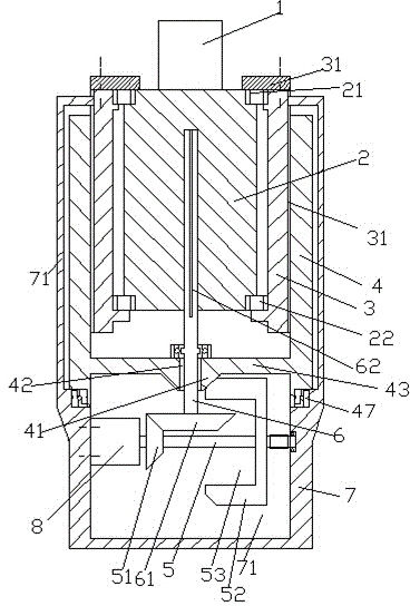
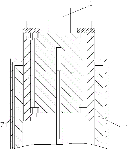
[0014] Attached below Figure 1-2 , the present invention will be described in detail.

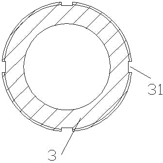
[0015] A spiral-rising processing equipment with four chutes for processing a blank 1 into a worm, the processing equipment includes a blank carrier 2, a sleeve 3 with external threads, and a drive sleeve with internal threads 4 and the frame 7, the blank carrier 2 is used to carry the blank 1, and the upper end and the lower end of the blank carrier 2 pass through the upper bearing 21 and the lower bearing 22 respectively relative to the sleeve 3 shafts with external threads It is fixedly installed in the sleeve 3 with external thread, and the sleeve 3 with external thread is screwed into the drive sleeve 4 with internal thread, and the drive sleeve 4 with internal thread The lower end of the frame 7 can be rotatably installed on the frame 7 through the thrust bearing 47, and the inside of the frame 7 has a chamber 72, and in the cavity 72, a driving motor is fixed on the left inner wall...


PUM


Abstract

The invention discloses spiral rising type processing equipment with four sliding grooves. The spiral rising type processing equipment is used for processing a blank piece (1) into a worm and comprises a blank-piece bearing piece (2), a sleeve (3) with external threads, a driving sleeve (4) with internal threads and a rack (7), wherein the blank-piece bearing piece (2) is used for bearing the blank piece (1); relative to the sleeve (3) with the external threads, the upper end and the lower end of the blank-piece bearing piece (2) are respectively and fixedly arranged in the sleeve (3) with the external threads by an upper bearing (21) and a lower bearing (22) in an axial manner; the sleeve (3) with the external threads is matched in the driving sleeve (4) with the internal threads by threads; the lower end of the driving sleeve (4) with the internal threads can be rotatably arranged on the rack (7) by a thrust bearing (47); the rack is internally provided with a cavity (72).

Description

technical field [0001] The present application relates to the field of worm processing, specifically a spiral-rising processing equipment with four chutes. Background technique [0002] The worm drive is composed of a worm and a worm gear, and the worm is generally the active part. Worms, like threads, can be divided into right-handed and left-handed. Worm drive has the following advantages: 1. Large transmission ratio and compact structure. The number of worm heads is represented by Z1 (generally Z1=1~4), and the number of worm gear teeth is represented by Z2. It can be seen from the transmission ratio formula I=Z2 / Z1 that when Z1=1, that is, the worm is single-headed, and the worm must turn Z2 to turn the worm wheel for one turn, so a large transmission ratio can be obtained. Generally, in power transmission, take The transmission ratio I=10-80; in the indexing mechanism, I can reach 1000. Such a large transmission, such as gear transmission, needs to adopt multi-stage...

Claims


Application Information

Patent Timeline
IPC IPC(8): B23F13/02B23Q5/28F16H37/02
Inventor 方小刚
Owner STATE GRID SHANDONG ELECTRIC POWER CO LONGKOU POWER SUPPLY CO
Why Eureka
Try Eureka