High pressure centrifugal slurry pump

A technology of centrifugal and slurry pumps, which is applied in the direction of non-variable pumps, non-volume pumps, pumps, etc. It can solve the problems of complex maintenance and management, high shaft seal pressure, and many workbenches, so as to improve operating conditions , Reduce the force, the effect of fewer seats

Inactive Publication Date: 2015-01-28
赵振海
View PDF6 Cites 1 Cited by
  • Summary
  • Abstract
  • Description
  • Claims
  • Application Information

AI Technical Summary

Problems solved by technology

As a result, there are many workbenches and high shaft seal pressure, while high-pressure seals use mechanical seals, and peripheral supporting equipment is required, and the reliability is poor, the cost is high, and the maintenance and management are complicated.

Method used


Image

  • High pressure centrifugal slurry pump
  • High pressure centrifugal slurry pump

Examples


Embodiment Construction

[0024] The present invention will be further described below in conjunction with accompanying drawing:

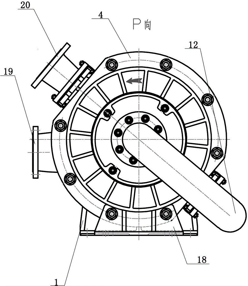
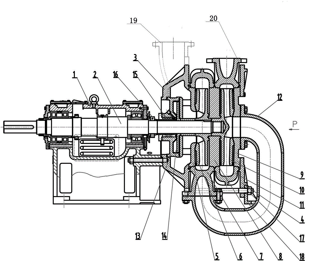
[0025] as attached figure 1 , 2 The embodiment of the present invention shown is a double-impeller high-pressure centrifugal slurry pump, and its bracket part 1 has the function of fixing and supporting the whole machine. The function of shaft 2 is to transmit torque, connect rotating parts, such as impeller A6, impeller B10 and auxiliary impeller 14, etc., and drive the impeller to do work on the slurry.

[0026] The joint plate 3 connects the bracket part 1 and the non-rotating parts of the pump, and guides the external slurry into the pump. In addition, together with the pump cover 4, the sealing box 13, the rear guard plate 5, the pump body A7, the middle guard plate 8, the pump body B11, the front guard plate 9, and the bracket 18 are connected together by bolt assemblies. Forms the fixed part of the working part of the pump.

[0027] The function of the conduit 12...


PUM


Abstract

The invention relates to a high pressure centrifugal slurry pump. The high pressure centrifugal slurry pump comprises a bracket part, a pump shaft and the like; a pump head with a double-impeller structure is arranged on the bracket part; the pump head comprises rotating parts, namely an impeller A, an impeller B and an auxiliary impeller, and fixed parts, namely a connecting plate, a pump cover, a seal box, a back protective plate, a pump body A, a middle protective plate, a pump body B, a front protective plate and a support; the outlet of the pump body B and the outlet of the pump body A are in 180-degree symmetry; a guide pipe is connected between the slurry outlet of the pump body A and the suction inlet of the impeller B; a framework oil seal structure is adopted between the seal box and the pump shaft; the support is arranged on the pump cover. The high pressure centrifugal slurry pump has high lift of 200 meters, does not require any external shaft seal facilities and can better meet the requirement on high pressure delivery.

Description

technical field [0001] The invention relates to a centrifugal slurry pump which can realize high-pressure slurry delivery and does not need peripheral shaft sealing equipment. technical background [0002] Centrifugal slurry pumps are widely used in national economic sectors such as metallurgy, iron and steel, mining, dredging, coal, electric power, petroleum, building materials, environmental protection, water conservancy projects, etc., to transport slurry containing different solid particles, and such slurry is widely used Has an abrasive effect on wetted parts. [0003] The typical structure of the commonly used slurry pump is shown in the attachment figure 1 . The head of this type of pump usually does not exceed 90 meters. When the long-distance transportation or the transportation height is high, the pump head is required to be high. At this time, multiple pumps must be used in series to meet the pressure requirements. As a result, there are many workbenches and ...

Claims


Application Information

Patent Timeline
Patent Type & Authority Applications(China)
IPC IPC(8): F04D7/04F04D29/10F04D29/14F04D29/20
CPCF04D1/06F04D7/04F04D29/102F04D29/143F04D29/185F04D29/20
Inventor 赵振海
Owner 赵振海
Why Eureka
Try Eureka