Distributive optical fiber detection method for mining overburden rock deformation

A technology of distributed optical fiber and detection method, which is applied in the direction of adopting optical devices, measuring devices, instruments, etc., to achieve the effects of easy installation, wide practicability and high precision

Active Publication Date: 2015-01-28
CHINA UNIV OF MINING & TECH
View PDF6 Cites 20 Cited by
  • Summary
  • Abstract
  • Description
  • Claims
  • Application Information

AI Technical Summary

Problems solved by technology

[0005] The purpose of the present invention is to solve the problems existing in the detection of deformation of overlying rock in existing mining, based on distributed optical fiber sensing technology, it has the advantages of long distance, good durability, high survival rate, strong anti-interference and good coordination performance with the measured object, etc. Advantages, providing a simple method, convenient operation, safe and reliable distributed optical fiber detection method for mining overburden deformation

Method used


Image

  • Distributive optical fiber detection method for mining overburden rock deformation
  • Distributive optical fiber detection method for mining overburden rock deformation
  • Distributive optical fiber detection method for mining overburden rock deformation

Examples


Embodiment 1

[0041] 1) Laying of sensing optical fiber 2:

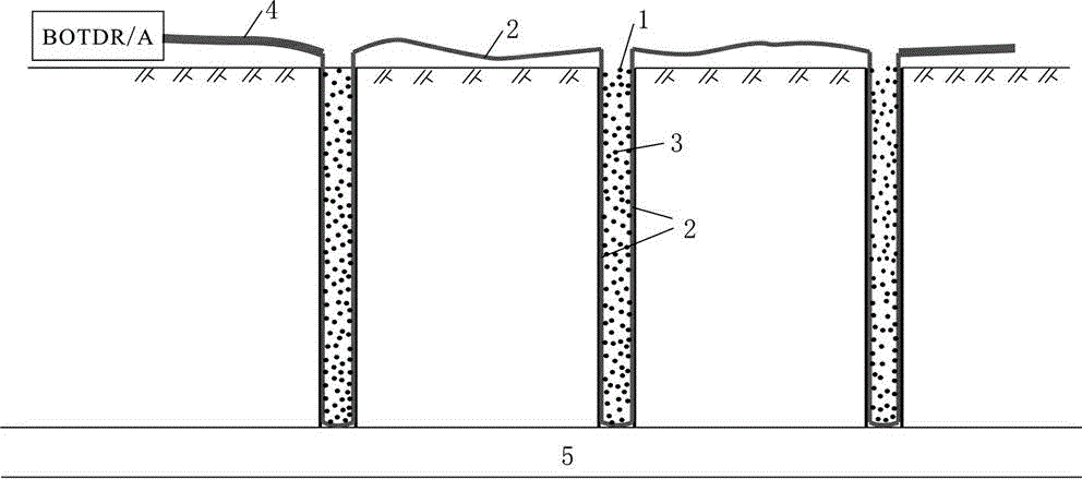
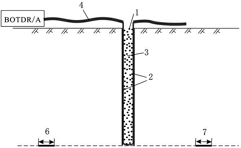
[0042] 1.1) Arrangement of monitoring holes. Boreholes 1 are arranged vertically from top to bottom every 10-50m along the mining direction of the working face. Boreholes 1 are variable-diameter holes whose diameter shrinks from the outside to the inside in stages. 110~200mm;

[0043] 1.2) Laying the sensing optical fiber 2, laying the sensing optical fiber 2 in a U-shape in the monitoring hole, the specific steps are:

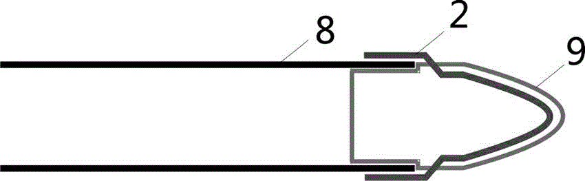
[0044]1.2.1) A counterweight 9 is provided for the drill pipe 8. The longitudinal section of the counterweight 9 is U-shaped, and its top port is provided with a connector that can match the inner diameter of the drill pipe 8. The side wall of the counterweight 9 is symmetrical There is a groove, the width and depth of the groove are 7-8mm respectively;

[0045] 1.2.2) Lay the sensing optical fiber 2 along the groove of the counterweight 9, paste the sensing optical fiber 2 in the counterweight 9 through epoxy r...

Embodiment 2

[0057] 1) Laying of sensing optical fiber 2:

[0058] 1.1) Arrange monitoring holes, drill holes 1 from bottom to top at the roof of air inlet lane 6 and air return lane 7 of mining face 5, and drill holes 1 in the same direction as the vertical line, and arrange vertically from bottom to top every 50m Monitoring hole, the monitoring hole is a variable diameter hole, its diameter shrinks in stages from the outside to the inside, and the range of the hole diameter is 110-200mm;

[0059] 1.2) Laying the sensing optical fiber 2, laying the sensing optical fiber 2 in a U-shape in the monitoring hole, the specific steps are:

[0060] 1.2.1) A counterweight 9 is provided for the drill pipe 8. The longitudinal section of the counterweight 9 is U-shaped, and its top port is provided with a connector that can match the inner diameter of the drill pipe 8. The side wall of the counterweight 9 is symmetrical A groove is provided, and the width and depth of the counterweight 9 are respect...

Embodiment 3

[0073] 1) Laying of sensing optical fiber 2:

[0074] 1.1) Arrange monitoring holes. Drill hole 1 from bottom to top at the roof of air inlet lane 6 and return air lane 7 of mining face 5. The direction of drill hole 1 is at an angle of α with the vertical line. The monitoring holes are arranged in a straight line, and the monitoring holes are variable-diameter holes, whose diameter shrinks from the outside to the inside in stages, and the range of the hole diameter is 110-200mm;

[0075] 1.2) Laying the sensing optical fiber 2, laying the sensing optical fiber 2 in a U-shape in the monitoring hole, the specific steps are:

[0076] 1.2.1) A counterweight 9 is provided for the drill pipe 8. The longitudinal section of the counterweight 9 is U-shaped, and its top port is provided with a connector that can match the inner diameter of the drill pipe 8. The side wall of the counterweight 9 is symmetrical There is a groove, the width and depth of the groove are 7-8mm respectively; ...


PUM


Abstract

The invention relates to a distributive optical fiber detection method for mining overburden rock deformation. According to the method, according to mining strata deformation features, drilling holes are arranged on the ground above a working face or the top plate of an intake airway or a ventilation airway of the working face, sensing optical fibers are buried in the drilling holes, concrete grout is adopted to seal the holes from inside to outside, and the reserved sensing optical fibers in the drilling holes are serially connected and are led to a monitoring room via a transmission optical cable. Initial value test is firstly carried out on the overburden rock body before mining, strata deformation caused by mining is measured when the working face approaches or is away facing the monitoring hole, the initial value is subtracted from the monitoring data of each frequency to serve as change values of the overburden rock of different time periods. Strain distribution of overburden rock deformation is obtained through analysis of the monitored data, overburden rock deformation damage height and stress condition caused by mining can be determined. The method has the advantages of being distributive, high in precision, simple and convenient in installation, and low in cost, and can be applied to the monitoring field of rock body deformation caused by various mining.

Description

technical field [0001] The invention relates to a detection method for rock formation movement in a coal mine stope, in particular to a distributed optical fiber detection method for deformation of overlying rock during mining. It is mainly used for distributed optical fiber detection of rock formation deformation during coal seam mining to determine the damage height and stress status of overlying rock deformation caused by mining. Background technique [0002] With the mining of the underground coal seam, the stress of the overlying rock mass will change. When the internal tensile stress exceeds the ultimate tensile strength of the rock layer, the rock layer will break, slip and separate layers, which will affect the safety of the roadway and the stability of the ground. . Therefore, it is of great significance to accurately detect the strain value and deformation and failure height of overlying strata caused by mining to evaluate roadway safety and formation maintenance....

Claims


Application Information

Patent Timeline
Patent Type & Authority Applications(China)
IPC IPC(8): G01B11/16
Inventor 朴春德施斌魏光庆袁骏
Owner CHINA UNIV OF MINING & TECH
Why Eureka
Try Eureka